- Top
- Description of Parts
- Recording module
- Right side
Right side
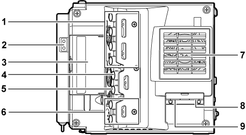
<SDI OUT1>/<SDI OUT2>/<SDI OUT3>/<SDI OUT4> terminal
Output terminal for 3G/HD SDI. This terminal outputs videos in SINGLE, DUAL, or QUAD mode.
For the cable to connect to this terminal, prepare a double-shielded cable equivalent to 5C-FB.
Light output terminal
Power supply terminal when light is connected.
<USB HOST> terminal (inside the cover, 5.0 V 0.5 A max)
For mounting the wireless module AJ-WM30/AJ-WM50 (optional).
For the cable to connect to this terminal, prepare a double-shielded cable.
<TC IN/OUT> terminal
Connects to the time code input terminal of the external device when locking the time code of the external device to the time code on the camera.
For the cable to connect to this terminal, prepare a double-shielded cable equivalent to 5C-FB.
<GENLOCK IN> terminal
Inputs reference signals when setting the genlock on the camera unit or when externally locking the time code. The input signal is 3G/HD-SDI.
For the cable to connect to this terminal, prepare a double-shielded cable equivalent to 5C-FB.
<MON OUT1>/<MON OUT2> terminal
3G/HD-SDI output terminal of videos for the monitor.
For the cable to connect to this terminal, prepare a double-shielded cable equivalent to 5C-FB.
Fan outlet
Fan outlet for dissipating heat. Do not block this when the camera is in use.
<USB DEVICE> terminal
USB device terminal for connecting a USB 2.0 cable.
For the cable to connect to this terminal, prepare a double-shielded cable.
<LAN> terminal
For connecting a LAN (100BASE-TX) cable.
For the cable to connect to this terminal, prepare a shielded cable.