- Top
- Description of Parts
- Left side
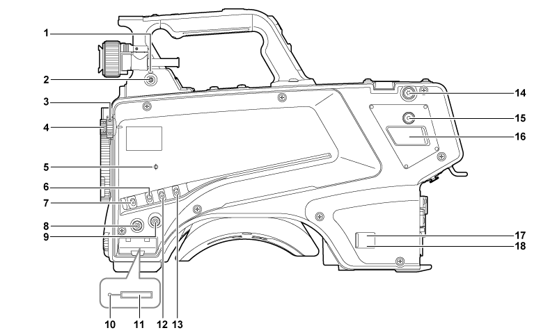
Left side
<LOCAL> lamp
While this lamp is lit, the <ND> filter and <CC> filter can be adjusted manually.
<FILTER LOCAL> switch
This switch sets whether to adjust the <ND> filter and <CC> filter manually or remotely.
<CC> filter dial
This dial selects the filter to suit the color temperature of the subject.
<A><3200K>: Sets the color temperature to 3200 K.
<B><4300K>: Sets the color temperature to 4300 K.
<C><6300K>: Sets the color temperature to 6300 K.
<D><CROSS>: Sets the cross filter.
<E><DF0>: Sets the diffusion filter.
<ND> filter dial
This dial selects the filter to suit the brightness of the subject.
<1><CAP>: Shuts out light from entering the MOS sensor.
<2><CLEAR>: Does not use the ND filter.
<3><1/4ND>: Reduces the amount of light entering the MOS sensor to 1/4.
<4><1/16ND>: Reduces the amount of light entering the MOS sensor to 1/16.
<5><1/64ND>: Reduces the amount of light entering the MOS sensor to 1/64.
<
 > mark
Indicates the focal plane of the MOS sensor.
Use this mark as a reference to accurately measure the focal distance from the subject.
<GAIN> switch
Switches the gain for the camera image. (<L>, <M>, <H>)
The gain can be configured with the CCU.
This switch cannot be used when the CCU or ROP is connected to the camera.
<DISP/MODE CHK> switch
This is a spring switch which can be used to check the shooting status etc.
Push this switch towards <OFF> to hide all displays except for the operation status display of the viewfinder, frame display such as an area, marker, and safety zone.
Push this switch towards <CHK> to display in the viewfinder the setting status for shooting functions, and the list of functions assigned to the <USER 1>/<USER 2>/<USER 3>/<USER 4> buttons, etc. Pushing the switch towards <CHK> again while information is being displayed switches the display to the next information page. The mode check information display disappears after approximately three seconds.
<MENU> button
Press this button to display the camera’s [MAIN MENU] screen.
Press the button again to return to the original image.
<USER 2> button
A user-selected function can be assigned to this button. Pressing the button performs the assigned function.
Busy (active status indicator) lamp
Indicates the active status of the SD memory card and lights up when the card is active.
SD memory card slot
This is the insertion slot for the SD memory card (optional).
An SD memory card is used for saving/loading the setting menus of the camera, loading CAC files, updating the software, etc.
For details, refer to “Data”.
<OUTPUT> switch
Switches video output (<CAM>, <BARS>, <TEST>).
This switch cannot be used when the CCU or ROP is connected to the camera.
<WHITE BAL> switch
Selects the white balance memory. Data can be recorded to <A> or <B>.
<PRST>: The white balance configured in [MAIN MENU] → [PAINT] → [COLOR TEMP SETTING] is set.
This switch cannot be used when the CCU or ROP is connected to the camera.
Shoulder strap fittings
Used to attach the shoulder strap.
<USER 4> button
A user-selected function can be assigned to this button. Pressing the button performs the assigned function.
<DC OUT 12V 2.5A> terminal
This terminal is a DC 12 V output terminal. It provides a maximum current of 2.5 A.
If the current exceeds the rating, the current will be cut off intermittently.
Power indicator lamp
Lights up in green when power is supplied to the camera.
ON (green): The camera power is on
ON (red): The camera power is off while the camera is connected to the CCU which is turned on
OFF: The camera power is off with the CCU not connected, or the camera is connected to the CCU which is turned off
<POWER> switch
Selects the camera power input, or turns off the power.
<CCU>: When the camera is connected to the CCU, this switch turns on the power with the power supplied from the CCU.
<EXT>: When an external DC power supply is connected to the camera, this switch turns on the power with the power supplied from the external DC power supply.
Center position: Turns off the power.