Connector pin assignment table
HA16PRH-5S (Hirose Electric Co., Ltd.)
Pin No. |
Function |
Remarks |
1 |
SHIELD |
Carbon MIC: -1 dB Dynamic MIC: -5 dB
|
2 |
TALK |
|
3 |
SHIELD |
|
4 |
RECEIVE |
|
5 |
NC |
JBY-25S-1A3F(LF)(SN) (J.S.T. Mfg. Co., Ltd.)
Pin No. |
Function |
Flow of signal |
Remarks |
1 |
INCOM ENG OUT (H) |
CCU→SYSTEM |
0 dBm, 600 Ω (4 W) / 1 V [p-p], 200 Ω (RTS) 4 W/RTS
|
2 |
INCOM ENG OUT (C) |
CCU→SYSTEM |
|
3 |
INCOM ENG (GND) |
||
4 |
INCOM ENG IN (H) |
SYSTEM→CCU |
|
5 |
INCOM ENG IN (C) |
SYSTEM→CCU |
|
6 |
PGM IN (H) |
SYSTEM→CCU |
0 dBm/-20 dBm, 600 Ω
|
7 |
PGM IN (C) |
SYSTEM→CCU |
|
8 |
PGM IN (GND) |
||
9 |
GND |
||
10 |
NC |
||
11 |
R TALLY IN (H) |
SYSTEM→CCU |
ON: Short/TTL(H)/24 V
OFF: Open/TTL(L)/0 V |
12 |
R TALLY IN (C) |
SYSTEM→CCU |
|
13 |
GND |
||
14 |
INCOM PROD OUT (H) |
CCU→SYSTEM |
0 dBm, 600 Ω (4 W) / 1 V [p-p], 200 Ω (RTS) 4 W/RTS
|
15 |
INCOM PROD OUT (C) |
CCU→SYSTEM |
|
16 |
INCOM PROD (GND) |
||
17 |
INCOM PROD IN (H) |
SYSTEM→CCU |
|
18 |
INCOM PROD IN (C) |
SYSTEM→CCU |
|
19 |
NC |
||
20 |
NC |
||
21 |
NC |
||
22 |
NC |
ON: Short/TTL(H)/24 V
OFF: Open/TTL(L)/0 V |
|
23 |
NC |
||
24 |
G TALLY IN (H) |
SYSTEM→CCU |
|
25 |
G TALLY IN (C) |
SYSTEM→CCU |

Example of tally input connections
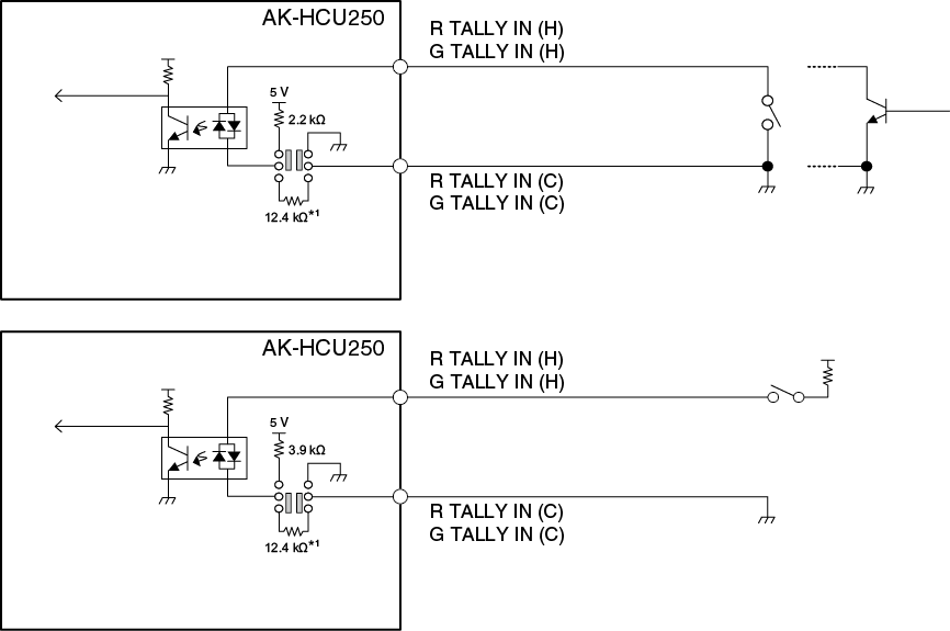
*1: Equivalent circuit
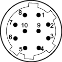
HR10G-10R-10SC (71) (Hirose Electric Co., Ltd.)
Pin No. |
Function |
Flow of signal |
1 |
ROP CONT (H) |
CCU→ROP |
2 |
ROP CONT (C) |
CCU→ROP |
3 |
ROP DATA (H) |
ROP→CCU |
4 |
ROP DATA (C) |
ROP→CCU |
5 |
NC |
|
6 |
NC |
|
7 |
NC |
|
8 |
NC |
|
9 |
+16 V OUT |
CCU→ROP |
10 |
GND |
- Connector of cable
HR10A-10P-10P (73)
HA16RV-3PG(76) (Hirose Electric Co., Ltd.)
Pin No. |
Function |
Flow of signal |
Remarks |
1 |
SHIELD |
0 dBm, 600 Ω |
|
2 |
HOT |
CCU→SYSTEM |
|
3 |
COLD |
CCU→SYSTEM |
- When connecting to an unbalanced input terminal of an external device, connect to it as shown in the diagram below.
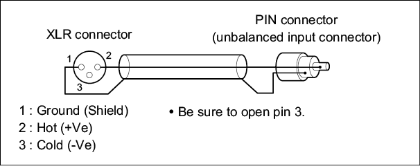
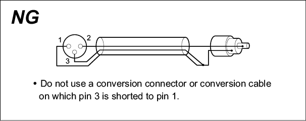
- Some commercially available conversion connectors and conversion cables have pin 3 shorted to pin 1.
Using such a conversion connector or conversion cable will cause a failure.
AK-HCU250P/AK-HCU250E: OPS2404-PR (Tajimi Electronics Co., Ltd.)
Pin No. |
Function |
Flow of signal |
1 |
Optical fiber |
CCU → CAM |
2 |
Optical fiber |
CAM → CCU |
3 |
DC 190 V (C) |
CCU → CAM |
4 |
DC 190 V (H) |
CCU → CAM |
5 |
Control line |
CCU ←→ CAM |
6 |
Control line |
CCU ←→ CAM |
AK-HCU250PS/AK-HCU250ES: FXW.3K.93C.TLM (LEMO)
Pin No. |
Function |
Flow of signal |
1 |
Optical fiber |
CCU → CAM |
2 |
Optical fiber |
CAM → CCU |
3 |
Control line |
CCU←→CAM |
4 |
Control line |
CCU←→CAM |
5 |
DC 190 V (H) |
CCU → CAM |
6 |
DC 190 V (C) |
CCU → CAM |