Front
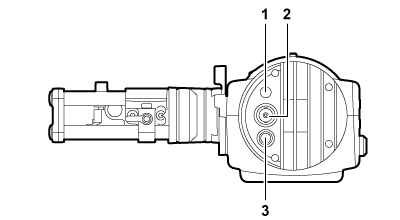
Tally LED
Lights up in red during recording or when red tally signals are received. This can be disabled in the viewfinder menu.
Video signal input terminal
An input terminal for 3G/HD-SDI video signal input.
Use the supplied BNC cable or the 5C-FB equivalent double-shielded cable for the cable to connect to this terminal.
<DC IN 12V> terminal
An input terminal for power supply input.
Connect to the electronic HD color view finder power supply terminal on the camera.
Use the supplied DC cable when connecting a cable to this terminal.
Using the external DC power supply
To use it by itself, connect the <DC IN 12V> terminal of the camera to the external DC power supply.
Connect after making sure that the output voltage of the external DC power supply is compatible with the rated voltage of the camera. When the power of the camera is turned on, inrush current is generated. Insufficient power supply when turning on the power may cause a malfunction. Use of the external DC power supply that can secure power more than twice the total power consumption of the camera is recommended. |
Make sure of the pin alignment of the DC output terminal of the external DC power supply and the camera <DC IN 12V> terminal, and connect the polarity correctly. Connecting the GND terminal to +12 V power supply by mistake may cause fire or malfunction. |
DC IN |
|---|
|
|
1 |
GND |
2 |
Data communication (from the viewfinder to the camera body) |
3 |
Data communication (from the camera body to the viewfinder) |
4 |
+12 V |
Cable connector HR10A-7R-4SC (73) (Hirose Electric Co.) |