- Top
- Description of Parts
- Rear side
Rear side
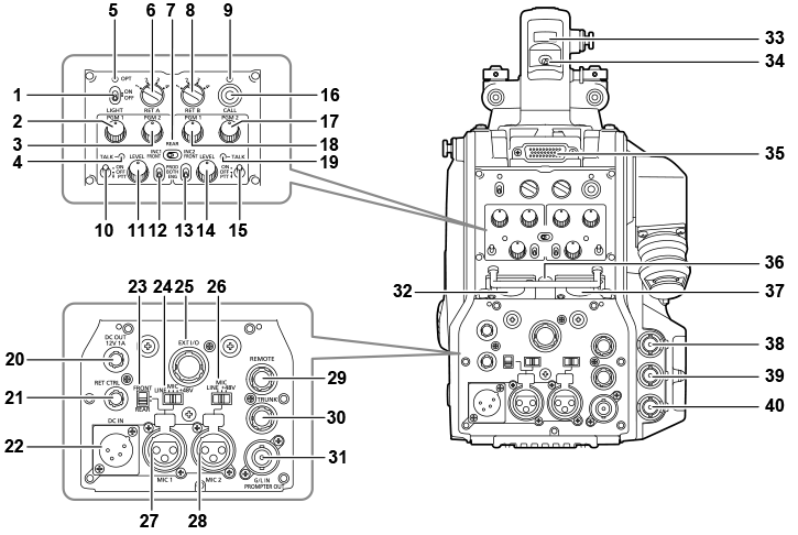
- <LIGHT> switch
- Used to turn the back panel lamp on/off.
- <PGM1> dial (<INTERCOM1>)
- Used to adjust the level of the audio or mixing ratio set from [MAIN MENU] → [INTERCOM SETTING] → [LEVEL/PGM1/PGM2 VR SETTING] → [INTERCOM1 PGM1 VR].
- <PGM2> dial (<INTERCOM1>)
- Used to adjust the level of the audio or mixing ratio set from [MAIN MENU] → [INTERCOM SETTING] → [LEVEL/PGM1/PGM2 VR SETTING] → [INTERCOM1 PGM2 VR].
- <TALK> lamp (<INTERCOM1>)
- Lights up when the <TALK> switch (<INTERCOM1>) is enabled.
- <OPT> lamp
- Indicates the camera’s optical signal reception status.
- Normal: Lit in green
- Error: Lit in red
 NOTE
NOTE- When an error has occurred, turn off the power of this camera and the CCU, and then clean the optical fiber connector. If the error persists, immediately turn off the power, and contact your dealer.
- <RET A> switch
- Used to switch the type of the return A image.
- <REAR>/<INC1 FRONT>/<INC2 FRONT> switch
- Used to switch the receiving target of the intercom.
- <REAR>: Adjusts the volume level of the intercom using the <LEVEL> dials of <INTERCOM1> and <INTERCOM2> on the rear side.
- <INC1 FRONT>: Adjusts the volume level of the intercom 1 using the <INCOM LEVEL> dial (front).
- <INC2 FRONT>: Adjusts the volume level of the intercom 2 using the <INCOM LEVEL> dial (front).
- <RET B> switch
- Used to switch the type of the return B image.
- <CALL> lamp
- Lights up in green when the call switch is pressed from the ROP or CCU.
- The lamp will flash in the following cases.
- When the <POWER> switch is set to <EXT>:
If the camera detects that the total current consumption including external DC output exceeds the rating, the lamp will flash in red.
If the camera detects that external DC output exceeds the rating, the lamp will flash in orange.
- When the <POWER> switch is set to <CCU>:
If the camera detects that the voltage supplied from the CCU is lower than the rating, the lamp will flash in red.
If the camera detects that external DC output exceeds the rating, the lamp will flash in orange.
NOTE- The voltage supplied from the CCU will change depending on the total power consumption which includes the following conditions.
Length of an optical fiber multi cable and the power consumption of the camera which includes the DC output
- The voltage supplied from the CCU will change depending on the total power consumption which includes the following conditions.
- When the <POWER> switch is set to <EXT>:
- <TALK> switch (<INTERCOM1>)
- This switch is the <ON>/<OFF>/<PTT> selector switch of the intercom microphone connected to the <INTERCOM1> terminal.
- Pushes the switch towards <ON>/<PTT> to turn on the microphone.
- <LEVEL> dial (<INTERCOM1>)
- Used to adjust the volume level of the intercom 1 when the mixing function of the intercom connected to the <INTERCOM1> terminal and the PGM is enabled. The mixing function of the intercom and the PGM can be enabled/disabled from [MAIN MENU] → [INTERCOM SETTING] → [INTERCOM1] → [INCOM1 RECEIVE CH1 SETTING] → [PGM1 MIX]/[PGM2 MIX].
- <PROD>/<BOTH>/<ENG> switch (<INTERCOM1>)
- Used to switch the call destination of the intercom connected to the <INTERCOM1> terminal.
- <PROD>/<BOTH>/<ENG> switch (<INTERCOM2>)
- Used to switch the call destination of the intercom connected to the <INTERCOM2> terminal.
- <LEVEL> dial (<INTERCOM2>)
- Used to adjust the volume level of the intercom 2 when the mixing function of the intercom connected to the <INTERCOM2> terminal and the PGM is enabled. The mixing function of the intercom and the PGM can be enabled/disabled from [MAIN MENU] → [INTERCOM SETTING] → [INTERCOM2] → [INCOM2 RECEIVE CH1 SETTING] → [PGM1 MIX]/[PGM2 MIX].
- <TALK> switch (<INTERCOM2>)
- This switch is the <ON>/<OFF>/<PTT> selector switch of the intercom microphone connected to the <INTERCOM2> terminal.
- Pushes the switch towards <ON>/<PTT> to turn on the microphone.
- <CALL> switch
- While this switch is pressed, the call lamps on the ROP and CCU are lit and the ROP buzzer sounds. (When the ROP buzzer setting is enabled)
NOTE
- If the <CALL> switch is pressed when the camera is operating with an external DC power source, the ROP call lamp does not light up.
- <PGM2> dial (<INTERCOM2>)
- Used to adjust the level of the audio or mixing ratio set from [MAIN MENU] → [INTERCOM SETTING] → [LEVEL/PGM1/PGM2 VR SETTING] → [INTERCOM2 PGM2 VR].
- <PGM1> dial (<INTERCOM2>)
- Used to adjust the level of the audio or mixing ratio set from [MAIN MENU] → [INTERCOM SETTING] → [LEVEL/PGM1/PGM2 VR SETTING] → [INTERCOM2 PGM1 VR].
- <TALK> lamp (<INTERCOM2>)
- This lamp is lit when the <TALK> switch (<INTERCOM2>) is enabled.
- <DC OUT 12V 1A> terminal
- This terminal is a DC 12 V output terminal. It provides a maximum current of 1.0 A.
- If the current exceeds the rating, the current will be cut off.
- Additionally, R and G tally signals are output. (Open collector type)
NOTE
- Immediately disconnect external equipment if the power supply to external equipment is cut off intermittently. Failure to do so may lead to a malfunction.
- When connecting external equipment, first fully check the polarities and current consumption. Failure to do so may lead to a malfunction.
- <RET CTRL> terminal
- This is the external control terminal. This terminal controls the on/off of the external return control switches 1, 2, 3 and the intercom microphone 1, 2. The return signal can be assigned from [MAIN MENU] → [RETURN SETTING] → [RETURN SELECT] → [RETURN C].
- <DC IN> terminal
- This is an input terminal for the external DC power supply. Connect an external DC power supply to this terminal. (DC 10.8 V to 17 V)
- <FRONT>/<REAR> selector switch
- Used to switch the microphone input signal of <MIC 1> to the front microphone or the rear microphone.
- <FRONT>: Front microphone
- <REAR>: Rear microphone
- <LINE/MIC/+48V> selector switch (<MIC 1>)
- Used to switch the audio input signal of the audio channel 1.
- <LINE>: When connecting audio equipment with the line input
- <MIC>: When connecting an external microphone
- <+48V>: When supplying 48 V power to the microphone
- <EXT I/O> terminal
- This is the external input and output terminal.
- <LINE/MIC/+48V> selector switch (<MIC 2>)
- Used to switch the audio input signal of the audio channel 2.
- <LINE>: When connecting audio equipment with the line input
- <MIC>: When connecting an external microphone
- <+48V>: When supplying 48 V power to the microphone
- <MIC 1> terminal
- This terminal is used to connect audio equipment or a microphone.
- The power for the microphone is supplied via this terminal, enabling use of a phantom powered (48 V) microphone. Turn the power off when connecting a microphone, and then configure the settings to suit the microphone after connecting the microphone.
- <MIC 2> terminal
- Used to connect audio equipment or a microphone.
- The power for the microphone is supplied via this terminal, enabling use of a phantom powered (48 V) microphone. Turn the power off when connecting a microphone, and then configure the settings to suit the microphone after connecting the microphone.
- <REMOTE> terminal
- Used to connect the remote control unit (optional) which can control some of the functions.
- <TRUNK> terminal
- This is an input/output terminal for the CCU trunk data (RS‑422 × 2 or RS‑232C × 2).
- Set this in [MAIN MENU] → [IN/OUT SELECT] → [TRUNK1]/[TRUNK2].
- <G/L IN/PROMPTER OUT> terminal
- This is the input terminal for genlock signals. The prompter video input from the CCU is output from this terminal.
- When the camera is used standalone, this terminal works as the genlock input. When connecting with the CCU, this terminal works as the prompter output.
NOTE
- Genlock can be applied to following signals when [MAIN MENU] → [SYSTEM MODE] → [FORMAT] is set to [2160/23.98p] or [1080/23.98p].
- HD-Y signal of 1080/23.98p or 1080/23.98PsF
- Composite signal
- Genlock can be applied to following signals when it is set to anything other than to [2160/23.98p] or [1080/23.98p].
- HD-Y signal of 1080/59.94i or 1080/50i
- Composite signal
- Genlock can be applied to following signals when [MAIN MENU] → [SYSTEM MODE] → [FORMAT] is set to [2160/23.98p] or [1080/23.98p].
- <INTERCOM1> terminal
- Used to connect the intercom or headset plug.
- Back tally lamp
- Lights up when the tally signal is supplied.
- R tally signal: Lit in red
- G tally signal: Lit in green
- R and G tally signals at the same time: Lit in red
- Back tally lamp selector switch
- Used to switch the back tally lamp to on/off.
- Rear viewfinder terminal
- Used to connect the 9-inch LCD viewfinder AK-HVF100G.
- This D-sub connector is used for the viewfinder interface.
NOTE
- AK-HVF70G, AK-HVF75G can also be connected to this terminal.
- <EARPHONE> terminal
- Used to connect the plug of a set of earphones.
- Configures the audio output from [MAIN MENU] → [INTERCOM SETTING] → [EAR PHONES SETTING] → [LCH OUTPUT SELECT]/[RCH OUTPUT SELECT].
- <INTERCOM2> terminal
- Used to connect the intercom or headset plug.
- <HD SDI1> terminal (BNC)
- [CAM]: Outputs camera images.
- [HD PROMPT]: Outputs HD prompter video images.
- Configure the output images in [MAIN MENU] → [IN/OUT SELECT] → [HD‑SDI1 OUT].
NOTE
- Use a cable that is 5C-FB or above.
- [HD PROMPT] can be selected only when the camera is connected to the CCU.
- <HD SDI2> terminal (BNC)
- [CAM]: Outputs camera images.
- [VF]: Outputs viewfinder images.
- [RET]: Outputs return images.
- [RET1]/[RET2]/[RET3]/[RET4]: Outputs the selected images.
- Configure the output images in [MAIN MENU] → [IN/OUT SELECT] → [HD‑SDI2 OUT].
NOTE
- Use a cable that is 5C-FB or above.
- [RET] and [RET1]/[RET2]/[RET3]/[RET4] can be selected only when the camera is connected to the CCU.
- <AUX> terminal
- This is the external device connecting terminal.
- [PMT2 OUT]: Outputs prompter 2 video images.
- [HD TRUNK]: HD trunk input
- Set this from [MAIN MENU] → [IN/OUT SELECT] → [AUX I/O].
NOTE
- Use a cable that is 5C-FB or above.
- If the HD trunk input is selected, only 1080/59.94i input is available when an input signal is 59.94 Hz; only 1080/50i input is available when an input signal is 50 Hz.