- Top
- Description of Parts
- Left side
Left side
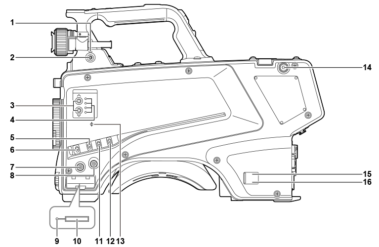
- <LOCAL> lamp
- While this lamp is lit, the ND filter can be adjusted manually.
- <FILTER LOCAL> switch
- This switch sets whether to adjust the ND filter manually or remotely.
- ND filter selector switch <ND FILTER>
- Pressing the <
 >/<
>/< > buttons switches between the optical filters.
 - <> (UP): CLEAR → 1/4 → 1/16 → 1/64...
- <> (DOWN): CLEAR → 1/64 → 1/16 → 1/4...
- ND filter selector LED
- The LED for the selected optical filter number lights up.
- <1>: CLEAR
- <2>: 1/4
- <3>: 1/16
- <4>: 1/64
- <GAIN> switch
- Switches the gain for the camera image. (<L>, <M>, <H>)
- The gain can be configured with the CCU.
- This switch cannot be used when the CCU or ROP is connected to the camera.
- <DISP/MODE CHK> switch
- This is a spring switch which can be used to check the shooting status etc.
- Push this switch towards <OFF> to hide all displays except for the operation status display of the viewfinder, frame display such as an area, marker, and safety zone.
- Push this switch towards <CHK> to display in the viewfinder the setting status for shooting functions, and the list of functions assigned to the <USER 1>/<USER 2>/<USER 3> buttons, etc. Pushing the switch towards <CHK> again while information is being displayed switches the display to the next information page. The mode check information display disappears after approximately three seconds.
- <MENU> button
- Press this button to display the camera’s [MAIN MENU] screen.
- Press the button again to return to the original image.
- <USER 2> button
- A user-selected function can be assigned to this button. Pressing the button performs the assigned function.
- Busy (active status indicator) lamp
- Indicates the active status of the SD memory card and lights up when the card is active.
 NOTE
NOTE- Do not remove or insert the card while this lamp is lit. Doing so may damage the SD memory card.
- SD memory card slot
- This is the insertion slot for the SD memory card (optional).
- An SD memory card is used for saving/loading the setting menus of the camera, loading CAC files, updating the software, etc.
- For details, refer to “Data”.
- <OUTPUT> switch
- Switches video output (<CAM>, <BARS>, <TEST>).
- This switch cannot be used when the CCU or ROP is connected to the camera.
- <WHITE BAL> switch
- Selects the white balance memory. Data can be recorded to <A> or <B>.
- <PRST>: The white balance configured in [MAIN MENU] → [PAINT] → [COLOR TEMP SETTING] is set.
- This switch cannot be used when the CCU or ROP is connected to the camera.
- <
 >mark
>mark - Indicates the focal plane of the CMOS sensor.
- Use this mark as a reference to accurately measure the focal distance from the subject.
- Shoulder strap fittings
- Used to attach the shoulder strap.
- Power indicator lamp
- Lights up in green when power is supplied to the camera.
- ON (green): The camera power is on
- ON (red): The camera power is off while the camera is connected to the CCU which is turned on
- OFF: The camera power is off with the CCU not connected, or the camera is connected to the CCU which is turned off
- <POWER> switch
- Selects the camera power input, or turns off the power.
- <CCU>: When the camera is connected to the CCU, this switch turns on the power with the power supplied from the CCU.
- <EXT>: When an external DC power supply is connected to the camera, this switch turns on the power with the power supplied from the external DC power supply.
- Center position: Turns off the power.