- Top
- Description of Parts
- Rear side
Rear side
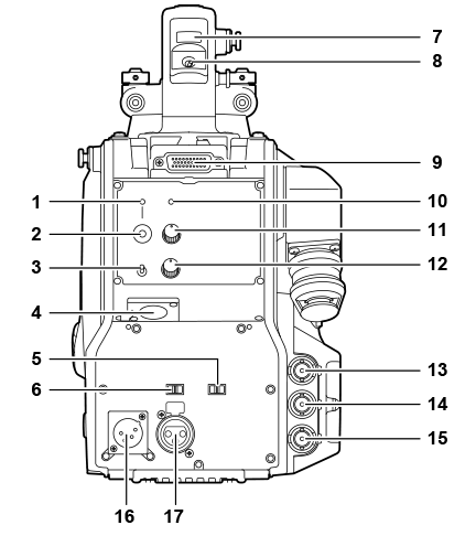
- <CALL> lamp
- Lights up in green when the call switch is pressed from the ROP or CCU.
- <CALL> switch
- While this switch is pressed, the call lamps on the ROP and CCU are lit and the ROP buzzer sounds. (When the ROP buzzer setting is enabled)
 NOTE
NOTE- If the <CALL> switch is pressed when the camera is operating with an external DC power source, the ROP call lamp does not light up.
- <TALK> switch (<INTERCOM>)
- This switch is the <ON>/<OFF>/<PTT> selector switch of the intercom microphone connected to the <INTERCOM> terminal.
- Pushes the switch towards <ON>/<PTT> to turn on the microphone.
- <INTERCOM> terminal
- Used to connect the intercom or headset plug.
- <LINE/MIC/+48V> selector switch (<FRONT MIC>)
- Used to switch the audio input signal of the audio channel 1.
- <LINE>: When connecting audio equipment with the line input
- <MIC>: When connecting an external microphone
- <+48V>: When supplying 48 V power to the microphone
- <LINE/MIC/+48V> selector switch (<MIC 2>)
- Used to switch the audio input signal of the audio channel 2.
- <LINE>: When connecting audio equipment with the line input
- <MIC>: When connecting an external microphone
- <+48V>: When supplying 48 V power to the microphone
- Back tally lamp
- Lights up when the tally signal is supplied.
- R tally signal: Lit in red
- G tally signal: Lit in green
- R and G tally signals at the same time: Lit in red
- Back tally lamp selector switch
- Used to switch the back tally lamp to on/off.
- Rear viewfinder terminal
- Used to connect the 9-inch LCD viewfinder AK-HVF100G.
- This D-sub connector is used for the viewfinder interface.
NOTE
- AK-HVF70G, AK-HVF75G can also be connected to this terminal.
- <OPT> lamp
- Indicates the camera’s optical signal reception status.
- Normal: Lit in green
- Error: Lit in red
NOTE
- When an error has occurred, turn off the power of this camera and the CCU, and then clean the optical fiber connector. If the error persists, immediately turn off the power, and contact your dealer.
- <PGM> dial (<INTERCOM>)
- Adjusts the mix level of the intercom and PGM.
- <LEVEL> dial (<INTERCOM>)
- Used to adjust the volume level of the intercom when the mixing function of the intercom connected to the <INTERCOM> terminal and the PGM is enabled. The mixing function of the intercom and the PGM can be enabled/disabled from [MAIN MENU] → [INTERCOM SETTING] → [INCOM RECEIVE SETTING] → [PGM MIX]
- <HD SDI1> terminal (BNC)
- [CAM]: Outputs camera images.
- [HD PROMPT]: Outputs HD prompter video images.
- Configure the output images in [MAIN MENU] → [IN/OUT SELECT] → [HD‑SDI1 OUT].
NOTE
- Use a cable that is 5C-FB or above.
- [HD PROMPT] can be selected only when the camera is connected to the CCU. Please also note that the video formats available for output are 1080/59.94p/50p/59.94i/50i.
- <HD SDI2> terminal (BNC)
- [CAM]: Outputs camera images.
- [VF]: Outputs viewfinder images.
- [RET]: Outputs return images.
- [RET1]/[RET2]: Outputs the selected images.
- Configure the output images in [MAIN MENU] → [IN/OUT SELECT] → [HD‑SDI2 OUT].
NOTE
- Use a cable that is 5C-FB or above.
- [RET] and [RET1]/[RET2] can be selected only when the camera is connected to the CCU.
- <AUX> terminal
- This is the external device connecting terminal.
- [PMT OUT]: Outputs prompter video images.
- [HD TRUNK]: HD trunk input
- Set this from [MAIN MENU] → [IN/OUT SELECT] → [AUX I/O].
NOTE
- Use a cable that is 5C-FB or above.
- The video formats available for input to [HD TRUNK] are 1080/59.94p/50p/59.94i/50i.
- <DC IN> terminal
- This is an input terminal for the external DC power supply. Connect an external DC power supply to this terminal. (DC 10.8 V to 17 V)
- <MIC 2> terminal
- Used to connect audio equipment or a microphone.
- The power for the microphone is supplied via this terminal, enabling use of a phantom powered (48 V) microphone. Turn the power off when connecting a microphone, and then configure the settings to suit the microphone after connecting the microphone.