- Top
- Description of Parts
- Shooting and recording/playback functions section
- Shooting and recording/playback functions section (Recording unit)
Shooting and recording/playback functions section (Recording unit)
<REC> button
Recording is started by pressing the <REC> button. Recording is stopped by pressing this button again.
Performs the same operation as the <VTR> button of the lens to be attached.
Card access lamp 1/card access lamp 2/card access lamp 3
Indicates the access status of recording and playback of the memory card.
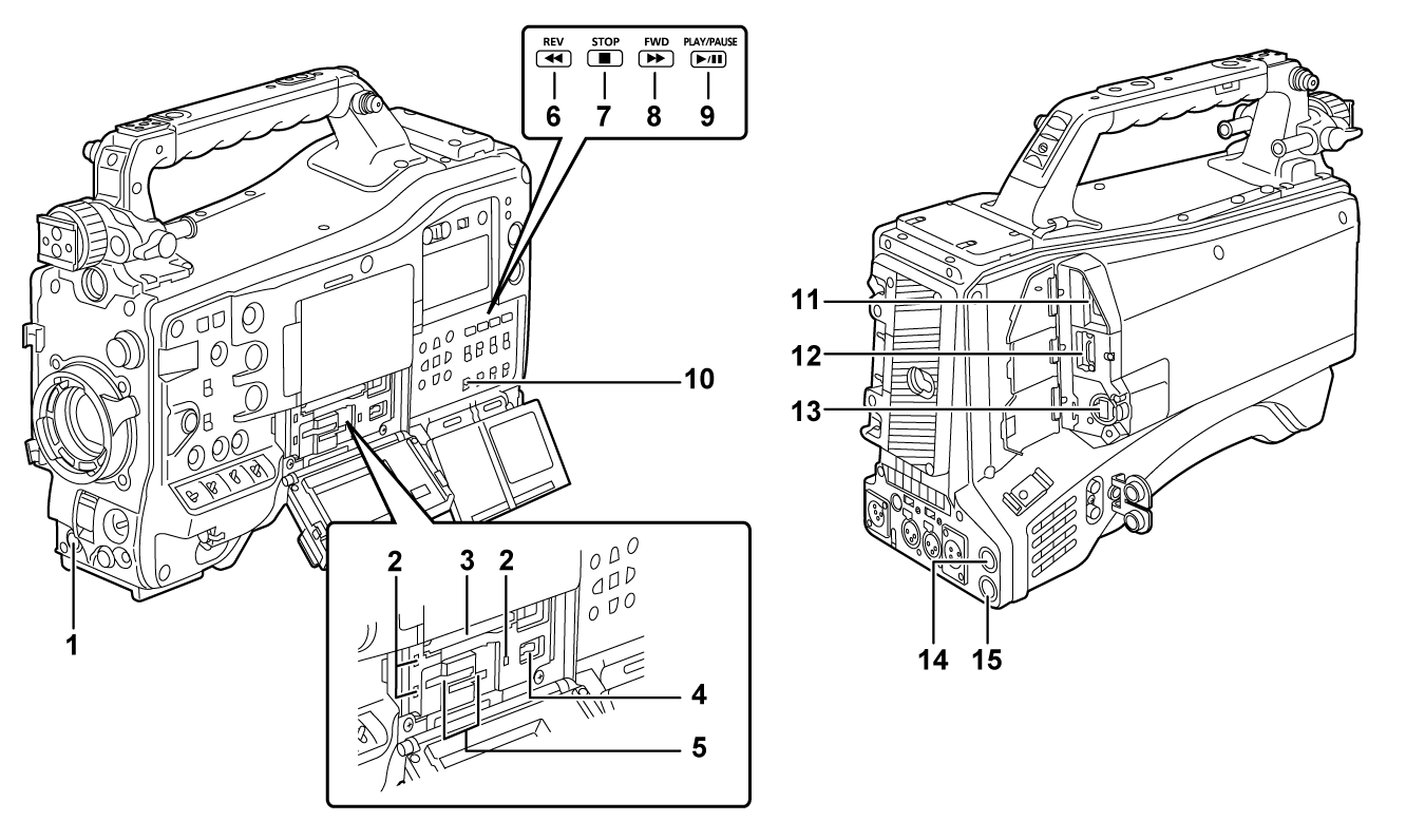
Card slot 1
This is a card slot only for expressP2 card.
<USB DEVICE> terminal
In the USB device mode, the camera can be connected to the computer by the USB type C cable to transfer data. In this case, recording playback operations and camera shooting are not possible.
Card slot 2/card slot 3
These are card slots for microP2 card and SD card.
<REV (
 )> button
It will perform fast-reverse playback when this is pressed during playback.
It will playback from the start of the clip when this is pressed while paused.
<STOP (
 )> button
Press this button to stop playback.
<FWD (
 )> button
It will perform fast playback when this is pressed during playback.
It will play back from the start of the next clip when this is pressed while paused during a playback.
<PLAY/PAUSE (
 /
/ )> button
Plays back a clip.
Playback is paused when this is pressed during the playback.
<SDI OUT 2 CHARACTER> switch
Controls the superimposing of characters into the video output from the <SDI OUT2> terminal.
Controls the superimposing of characters into the video output from the <HDMI> terminal when the [VIDEO OUT/LCD/VF] menu → [HDMI OUT] → [SIGNAL SEL] → [SDI OUT2] is set.
<ON>: Superimposes the character.
<OFF>: Does not superimpose the character.
<USB2.0 HOST> terminal
Can connect via wireless LAN when the wireless module (optional) compatible to camera is mounted.
In addition, connecting the USB cable and iPhone/iPad or Android device will enable to connect to the network using USB tethering.
<HDMI> terminal
This is the output terminal for videos.
Output signal can be switched with the [VIDEO OUT/LCD/VF] menu → [HDMI OUT] → [SIGNAL SEL].
[SDI OUT1(2160p)]: Follows the setting of the output signal from the <SDI OUT1> terminal.
[SDI OUT2]: Follows the setting of the output signal from the <SDI OUT2> terminal.
Setting for superimposing of characters can be switched in the [VIDEO OUT/LCD/VF] menu → [HDMI OUT] → [SIGNAL SEL].
<LAN> terminal
Connects the 1000BASE-T/100BASE-TX/10BASE-T LAN cable.
Use Category 7 LAN cable.
<SDI OUT1> terminal
This is the output terminal only for SDI.
Select an output signal in the [VIDEO OUT/LCD/VF] menu → [SDI OUT1] → [OUT FORMAT].
Superimposing of characters is set in the [VIDEO OUT/LCD/VF] menu → [SDI OUT1] → [SDI OUT CHAR].
<SDI OUT2> terminal
This is the video output terminal for the monitor.
Select an output signal in the [VIDEO OUT/LCD/VF] menu → [SDI OUT2] → [OUT FORMAT].
Superimposing of characters can be set with the <SDI OUT 2 CHARACTER> switch independently of the <SDI OUT1> terminal.