- Top
- Description of Parts
- Shooting and recording/playback functions section
- Shooting and recording (Camera unit)
Shooting and recording (Camera unit)
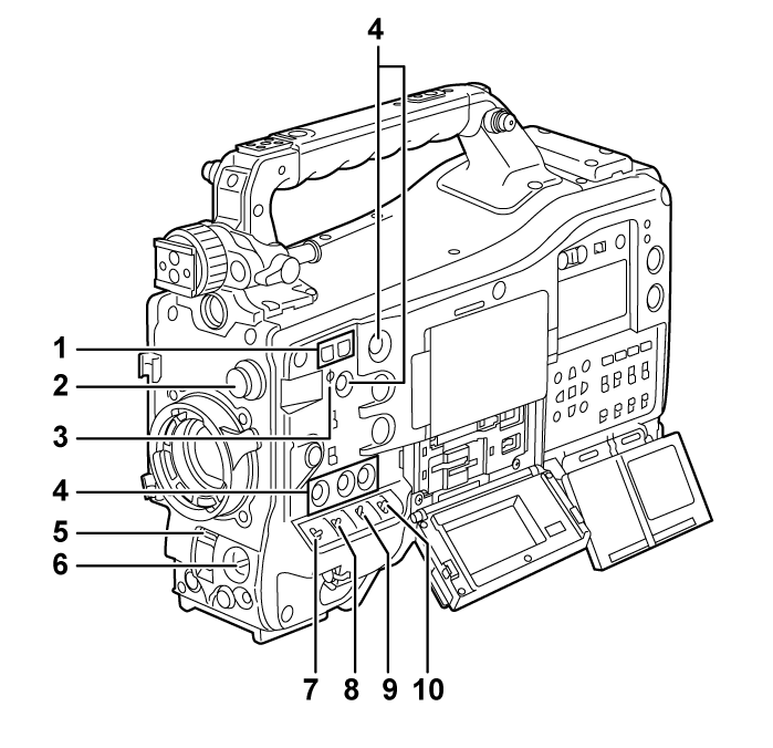
<SYNCHRO SCAN> button
Adjusts the shutter speed of synchro scan in the synchro scan mode.
Pressing the <−> button slows down the shutter speed. Pressing the <+> button increases the shutter speed.
For example, when shooting a computer monitor, adjust to a position where the noise for the horizontal bar in the viewfinder will be reduced.
<CC FILTER>/<ND FILTER> dial
Select the filter to suit the luminance or color temperature of the subject.
Position of <CC FILTER> dial (large diameter)
Setting
Description
<A>
<3200 K>
Sets the color temperature to 3200 K.
<B>
<4300 K>
Sets the color temperature to 4300 K.
<C>
<5600 K>
Sets the color temperature to 5600 K.
<D>
<6300 K>
Sets the color temperature to 6300 K.
Position of <ND FILTER> dial (small diameter)
Setting
Description
<1>
<CLEAR>
Does not use the ND filter.
<2>
<1/4ND>
Reduces the amount of light entering the MOS sensor to 1/4.
<3>
<1/16ND>
Reduces the amount of light entering the MOS sensor to 1/16.
<4>
<1/64ND>
Reduces the amount of light entering the MOS sensor to 1/64.
Refer to the following table to switch the <CC FILTER> and <ND FILTER> dials according to the shooting conditions.
Shooting conditions
<CC FILTER> dial
<ND FILTER> dial
Sunset, sunrise, inside studio
<A> (<3200 K>)
<1> (<CLEAR>)
Outdoors in the clear skies
<B> (<4300 K>) or <C> (<5600 K>) or <D> (<6300 K>)
<2> (<1/4ND>) or <3> (<1/16ND>)
Outdoors under cloudy skies or in the rain
<D> (<6300 K>)
<1> (<CLEAR>) or <2> (<1/4ND>)
Clear, bright scenery such as snowy scenery, tall mountains, seaside
<B> (<4300 K>) or <C> (<5600 K>) or <D> (<6300 K>)
<3> (<1/16ND>) or <4> (<1/64ND>)
Focal plane index <
 >
>Indicates the focal plane of the MOS sensor.
Use this mark as a reference for measuring the accurate focal distance from the subject.
USER button
The function selected by the user can be assigned to the <USER 1> to <USER 5> buttons. Pressing the USER button performs the assigned function.
<SHUTTER> switch
Switches the electronic shutter.
<OFF>: Disables the electronic shutter.
<ON>: Enables the electronic shutter.
<SEL>: Changes the shutter speed.
It is a spring switch. Shutter speed is changed each time pressed toward the <SEL> side.
<AUTO W/B BAL> switch
<AWB>: White balance is automatically adjusted. When this switch is operated with the <WHITE BAL> switch on the side set to <A> or <B>, adjustment is performed in several seconds and adjustment values are stored in memory.
This is disabled when the <WHITE BAL> switch is set to <PRST>.
<ABB>: Adjusts black balance automatically.
The black shading automatic adjust function can be assigned to this switch when set to the [CAMERA] menu → [SW MODE] → [SHD,ABB SW CTL] → [ON].
The automatic adjustment is cancelled when operation of switch is repeated while auto adjustment is performed. The adjustment values will return to the values before automatic adjustment was performed.
<MARKER SEL>/<MODE CHECK> switch
This is the spring switch to select a maker and check the shooting status of the camera.
<MKR>: Every time this is pressed to the <MKR> side, the marker display on the viewfinder switches in the order of [A] marker, [B] marker, and no display.
When the power is turned on, the status before the power was turned off is applied.
<MCK>: Every time this is pressed to the <MCK> side, display is switched in the order of STATUS screen, !LED screen, FUNCTION screen, AUDIO screen, CAC screen, SWITCH screen, NETWORK screen, and camera image screen. This does not affect the output signals from the camera. The display goes out in about five seconds. When the switch is continued to be pressed toward the <MCK> side, the selected screen remains displayed.
<GAIN> switch
Switches the video amplifier gain according to the lighting conditions when shooting.
Set the gain value for <L>/<M>/<H> in the [SCENE FILE] menu → [LOW SETTING]/[MID SETTING]/[HIGH SETTING] → [MASTER GAIN] in advance.
The factory setting is L=0 dB, M=6 dB, H=12 dB.
<OUTPUT>/<AUTO KNEE> switch
Select the video signals output to the memory, viewfinder and video monitor from the camera unit.
<CAM>/<ON>: Video captured on the camera is output and the auto knee function is activated.
Instead of the auto knee function, the dynamic range stretcher (DRS) function can be assigned.
<CAM>/<OFF>: Video captured on the camera is output and the auto knee function is not activated.
The knee point is fixed to the level set in the [SCENE FILE] menu → [KNEE SETTING] → [KNEE MASTER POINT].
<BARS>/<OFF>: The color bar signal is output. The auto knee function is not activated.
The color bar signal can be selected from the two types in the [OTHERS] menu → [COLOR BARS] → [COLOR BARS TYPE].
<WHITE BAL> switch
Switches the white balance adjustment method.
<PRST>: Set the switch to this position when there is no time to adjust the white balance.
The factory setting is 3200 K.
Can be changed to an arbitrary color temperature with the [CAMERA] menu → [WHITE BALANCE MODE] → [W.BAL VAR].
<A>/<B>: When the <AUTO W/B BAL> switch is pressed to the <AWB> side, the white balance is automatically adjusted and the adjusted value is saved in memory A or memory B.
The auto tracking white balance (ATW) function can be assigned to the <WHITE BAL> switch with the [CAMERA] menu → [WHITE BALANCE MODE] → [ATW].