- Top
- Description of Parts
- Rear side
Rear side
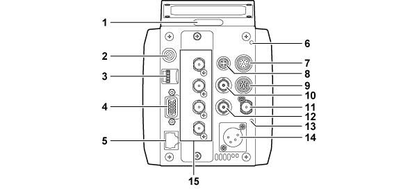
Back tally lamp
Lights up when the tally signal is supplied.
Blinks in red while displaying warning, and blinks in green during the firmware update.
<MENU> button
Press this button to display the camera’s [MAIN MENU] screen.
Press the button again to return to the original image.
Jog dial button
This will perform the navigation of setting menu pages, and selection or setting of the item when the setting menu is displayed.
The cursor will move down when the jog dial button is turned downward. The cursor will move up when turned upward.
Press the jog dial button to fix the settings.
<I/F> terminal
Connect the cable for the external synchronization signal and the control signal to the camera.
For specification of the connection cable, refer to “Details of the connector signals”.
<LAN> terminal
Used to connect the LAN cable.
<WARNING> lamp
This will illuminate in red when a problem occurs.
<IRIS> terminal
Used to connect the lens iris control cable.
<TALLY OUT> terminal
Outputs R tally and G tally.
<ZOOM/FOCUS> terminal
Used to connect the lens zoom/focus control cable.
<HD SDI OUT 1> terminal
This is the main line output terminal dedicated for HD SDI.
<G/L IN> terminal
This is the reference signal input terminal when applying external synchronization to the camera.
<HD SDI OUT 2> terminal
This is the monitor output terminal dedicated for HD SDI.
<DC IN> lamp
This will illuminate in green when power is supplied to the camera.
<DC IN> terminal
This is an input terminal for the external DC power supply. Connects to the external DC power supply. (DC 11 V to 17 V)
<UHD/HD SDI OUT 1>/<UHD/HD SDI OUT 2>/<UHD/HD SDI OUT 3>/<UHD/HD SDI OUT 4> terminal
These are the UHD and HD SDI main line output terminals.