- Top
- Picture monitor (PM)
- Information display
- Status displays
Status displays
From the IRIS display screen, press the [CHARA] button of the ROP to display the “status display screen”.
However, when the “IRIS LEVEL” setting is “OFF”, the screen will be displayed first if the [CHARA] button of the ROP is pressed when the information is not displayed on the picture monitor.
When the “status display screen” appears, pressing the [CHARA] button of the ROP again displays the status screen.
Pressing the [CHARA] button repeatedly switches display through the status screens in the sequence 1/7 → 2/7 → 3/7 → 4/7 → 5/7 → 6/7 → 7/7 → 1/7 ….
Status display screen
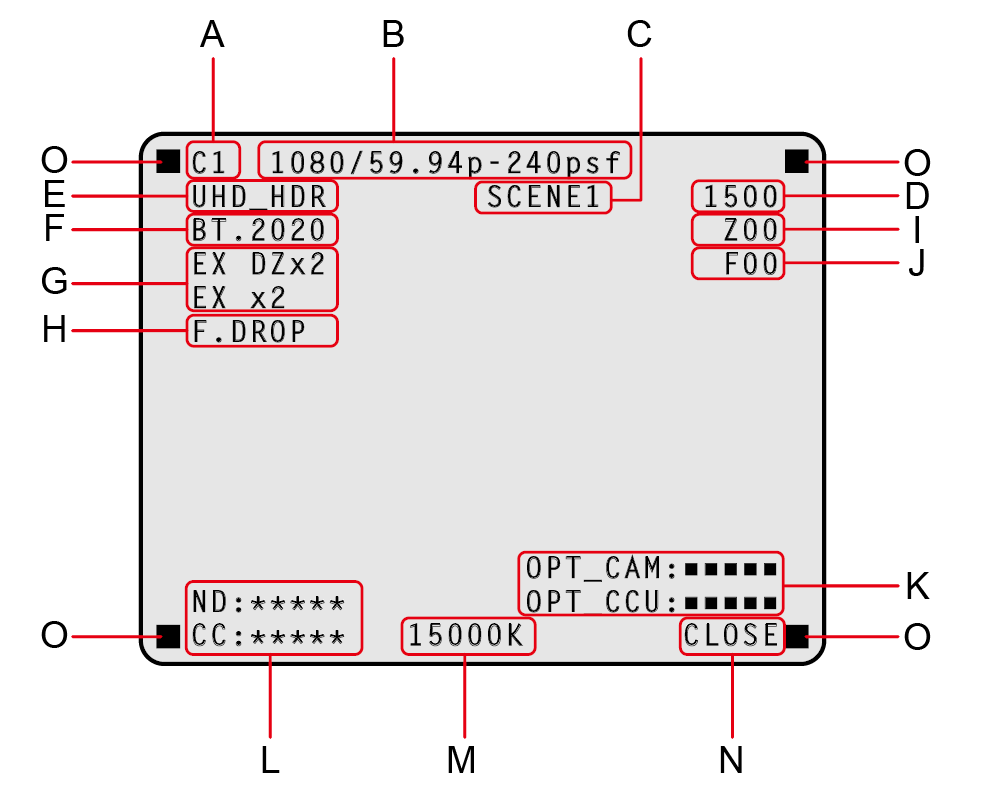
A.Camera number
B.System format
C.Scene file number
Not displayed when SCENE FILE is set to OFF.
D.Shutter value
E.CCU format information
F.COLORIMETRY (Y/C conversion coefficient) information
G.Extender information
H.Lens information
I.Zoom position
J.Focus position
K.Optical signal reception status (camera and CCU)
L.ND/CC filter value
The CC filter value is not displayed when AK-UC3300 and AK-PLV100 are connected.M.Color temperature
N.IRIS F value
O.TALLY INFO
- Set each item to be displayed on the [PM VIEW SETTING] screen that can be accessed by selecting [MAINTENANCE] on the CCU menu.
- The camera format indicates the format of the signal output from the camera.
- Pressing the [CHARA] button of the ROP from the status display screen displays the “status screen”.
- TALLY INFO (L)
- Display the R tally in two segments of the upper row and the R, G, or YL tally in two segments of the lower row.
- When all R, G, and YL tally signals are ON, the upper row is red, and the left and right segments of the lower row are green and yellow, respectively.
- When the R and G tally signals are ON, the upper row is red and the lower row is green.
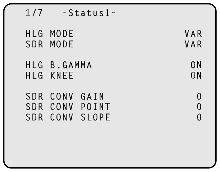
Status displays (page 1 of 7)
|
Item |
Display range |
Remarks |
|---|---|---|
|
HLG MODE |
FIX VAR |
The HLG mode is displayed here. |
|
SDR MODE |
FIX VAR |
The SDR mode is displayed here. |
|
HLG B.GAMMA |
OFF ON |
The status of black gamma when HLG is enabled is displayed here. |
|
HLG KNEE |
OFF ON |
The status of knee when HLG is enabled is displayed here. |
|
SDR CONV GAIN |
–12 –11 –10 –9 –8 –7 –6 –5 0 |
The gain value when HDR video is converted to SDR video is displayed here. |
|
SDR CONV POINT |
0 to 100 |
The video level to start compression for SDR video is displayed here. |
|
SDR CONV SLOPE |
0 to 127 |
The slope to compress video signals is displayed here. |
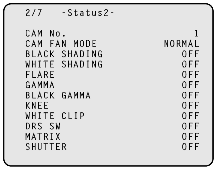
Status displays (page 2 of 7)
|
Item |
Display range |
Remarks |
|---|---|---|
|
CAM No. |
1 to 99 |
The camera number is displayed here. |
|
CAM FAN MODE |
OFF POWERFUL SILENT NORMAL |
Indicates the operational mode of the camera fan. |
|
BLACK SHADING |
OFF ON |
The status of the black shading is displayed here. |
|
WHITE SHADING |
OFF ON |
The status of the white shading is displayed here. |
|
FLARE |
OFF ON |
The status of the FLARE is displayed here. |
|
GAMMA |
OFF ON |
The status of the gamma correction is displayed here. |
|
BLACK GAMMA |
OFF ON |
The status of the black gamma is displayed here.
|
|
KNEE |
OFF ON |
The status of the knee function is displayed here.
|
|
WHITE CLIP |
OFF ON |
The status of the white clip function is displayed here. |
|
DRS SW |
OFF ON |
The status of the DRS SW is displayed here. |
|
MATRIX |
OFF ON |
The status of the matrix function is displayed here.
|
|
SHUTTER |
Setting values on camera |
The speed of the electronic shutter is displayed here.
|
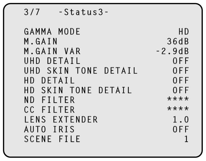
Status displays (page 3 of 7)
|
Item |
Display range |
Remarks |
|---|---|---|
|
GAMMA MODE |
HD FILMLIKE1 FILMLIKE2 FILMLIKE3 FILM REC VIDEO REC |
The selected gamma type is displayed here. |
|
M.GAIN |
-6dB to 36dB |
The gain increase value is displayed here. |
|
M.GAIN VAR |
-2.9dB to +2.9dB |
The gain offset value is displayed here. |
|
UHD DETAIL |
OFF ON |
The status of the UHD DETAIL is displayed here. |
|
UHD SKIN TONE DETAIL |
OFF ON |
Indicates the status of the SKIN TONE DETAIL function.
|
|
HD DETAIL |
OFF ON |
The status of the HD DETAIL is displayed here. |
|
HD SKIN TONE DETAIL |
OFF ON |
Indicates the status of the SKIN TONE DETAIL function.
|
|
ND FILTER |
**** |
The names of the ND filters are displayed here.
|
|
CC FILTER |
**** |
The names of the CC filters are displayed here.
|
|
LENS EXTENDER |
1.0 2.0 |
The magnification of the lens extender is displayed here. |
|
AUTO IRIS |
OFF ON |
The status of the auto IRIS function is displayed here. |
|
SCENE FILE |
OFF --- 1 to 8 |
The selected scene file is displayed here. |
Status displays (page 4 of 7)
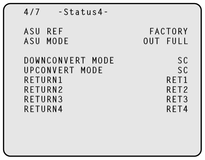
|
Item |
Display range |
Remarks |
|---|---|---|
|
ASU REF |
FACTORY USER1 USER2 USER3 REF1 REF2 REF3 |
The reference file used during auto setup is displayed here.
|
|
ASU MODE |
OUT FULL OUT EASY |
The auto setup mode is displayed here.
|
|
DOWNCONVERT MODE |
SC SQ LB LINK |
The downconversion mode is displayed here. The displayed abbreviations represent the following. SC: SIDECUT SQ: SQUEEZE LB: LETTERBOX LINK: LINK |
|
UPCONVERT MODE |
SC SQ LB LINK |
The upconversion mode is displayed here. The displayed abbreviations represent the following. SC: SIDECUT SQ: SQUEEZE LB: LETTERBOX LINK: LINK |
|
RETURN1 |
RET1 RET2 RET3 RET4 VBS |
The statuses of the input format allocations for SDI return signals 1 to 4 are displayed here. |
|
RETURN2 |
||
|
RETURN3 |
||
|
RETURN4 |
Status displays (page 5 of 7)
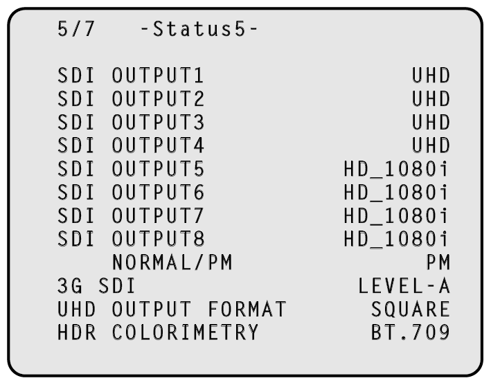
|
Item |
Display range |
Remarks |
|---|---|---|
|
SDI OUTPUT1 |
UHD 3G HD UHD_HDR HD_HDR HD_SDR |
Output formats of SDI OUT1 through SDI OUT4 are displayed here. |
|
SDI OUTPUT2 |
||
|
SDI OUTPUT3 |
||
|
SDI OUTPUT4 |
||
|
SDI OUTPUT5 |
UHD 3G HD_1080i HD_1080p HD_720p UHD_HDR 3G_HDR HD_HDR_1080i HD_HDR_1080p HD_SDR_1080i HD_HDR_720p |
Output formats of SDI OUT5 through SDI OUT7 are displayed here. |
|
SDI OUTPUT6 |
||
|
SDI OUTPUT7 |
||
|
SDI OUTPUT8 |
HD_1080i HD_1080p HD_720p HD_HDR_1080i HD_HDR_1080p HD_SDR_1080i HD_HDR_720p |
Output format of SDI OUT8 is displayed here. |
|
SDI OUTPUT8 NORMAL / PM |
PM NORMAL |
The signal to be output from SDI OUT8 is displayed here. |
|
3G SDI |
LEVEL-A LEVEL-B |
The output format during 3G output is displayed here. |
|
UHD OUTPUT FORMAT |
INTERLEAVE SQUARE |
The format (INTERLEAVE or SQUARE) of the UHD signals output from SDI OUT1 to SDI OUT4 is displayed here. |
|
HDR COLORIMETRY |
BT.709 BT.2020 |
The Y/C conversion coefficient is displayed here. |
Status displays (page 6 of 7)
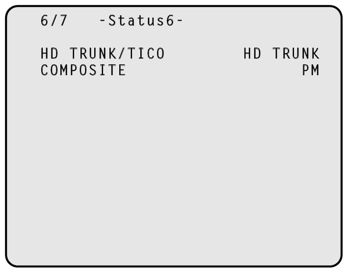
|
Item |
Display range |
Remarks |
|---|---|---|
|
HD TRUNK/TICO |
HD TRUNK TICO |
The signal to be output from the [HD TRUNK OUT] connector is displayed here. |
|
COMPOSITE |
PM NORMAL |
The signal to be output from the [VBS PM OUT] connector is displayed here. |
Status displays (page 7 of 7)
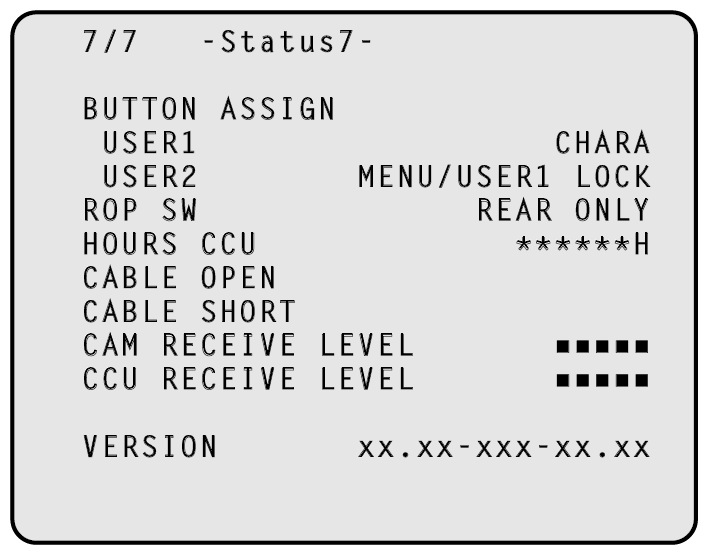
|
Item |
Display range |
Remarks |
|---|---|---|
|
BUTTON ASSIGN USER1 |
NONE CHARA BARS CLEAN |
The function assigned to the [USER1] button is displayed here. |
|
BUTTON ASSIGN USER2 |
NONE CHARA MENU/USER1 LOCK BARS CLEAN |
The function assigned to the [USER2] button is displayed here. |
|
ROP SW |
FRONT ONLY REAR ONLY SWITCH SELECT |
This displays the operating status (front/rear) of the [ROP] connectors. |
|
HOURS CCU |
******H |
Cumulative CCU operating time is displayed here. |
|
CABLE OPEN |
(Off) |
This item flashes when the optical fiber multi cable is not connected. |
|
CABLE SHORT |
(Off) |
This item flashes when the optical fiber multi cable is short-circuited. |
|
CAM RECEIVE LEVEL |
■■■■■ |
The level of the optical signals received by the camera is displayed in 5 gradations. |
|
CCU RECEIVE LEVEL |
■■■■■ |
The level of the optical signals received by the unit is displayed in 5 gradations. |
|
VERSION |
- - - |
The unit's software version is displayed here. |