- Top
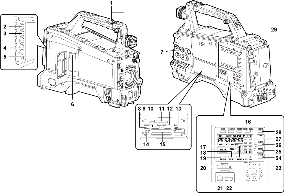
- Description of parts
- Shooting and recording/playback functions section
- Shooting and recording/playback functions section (recording unit)
Shooting and recording/playback functions section (recording unit)
<REC> button (For shooting)
Press this button to start recording. Press it again to stop recording.
This button has the same function as the VTR button on the lens side.
<SDI OUT1> terminal (Selecting video output from each terminal)
This is the output terminal for SDI signal. Output is performed in the same signal format as in the system mode. Down-conversion and up-conversion are not supported.
<GL IN/VIDEO OUT> terminal (Externally locking the time code)
This is the input terminal for reference signals when setting the genlock to the camera unit. This is also the output terminal for the VBS signal for monitor. Switch the setting using the main menu → [IN/OUT SEL] → [GL IN/VIDEO OUT SEL].
<SDI OUT2/IN> terminal (Selecting video output from each terminal)
This is the output terminal for the SDI signal for monitor. This is also the input terminal for SDI signal. Switch with the main menu → [IN/OUT SEL] → [SDI OUT2/IN SEL]. Video independent from the <SDI OUT1> terminal can be output. Also, the HD SDI signal or the down-converted SD SDI signal can be selected in the [SET02:MON OUT SELECT] screen of SmartUI. Cross-conversion and up-conversion are not supported.
<LAN> terminal (For wired LAN)
Connect the LAN cable.
<USB2.0> terminal (sub-host) (For wireless module AJ-WM30/AJ-WM50, For wireless module other than AJ-WM30/AJ-WM50)
Mount the wireless module AJ-WM30/AJ-WM50 (optional). Or, attach the USB 2.0 extension cable connecting the body and the 4G/LTE USB modem (optional).
<FOCUS ASSIST> button (Focus assist function)
Switch on/off the focus assist function.
microP2 memory card 1 access LED (P2 card access LEDs and status of P2 cards)
Indicate the access status of recording and playback of the card inserted in the microP2 memory card slot 1.
microP2 memory card slot 1 (Inserting a P2 card)
Busy (active status indication) lamp (Removing SD memory cards)
Indicate the active status of the SD memory card, and is illuminated when the card is active.
SD memory card slot (Inserting SD memory cards)
This is the insertion slot for the SD memory card (optional). Use the SD memory card for recording/opening the setting menu and scene files for the camera, uploading metadata, or proxy recording, etc.
microP2 memory card 2 access LED (P2 card access LEDs and status of P2 cards)
Indicate the access status of recording and playback of the card inserted in the microP2 memory card slot 2.
microP2 memory card slot 2 (Inserting a P2 card)
P2 memory card access LED (P2 card access LEDs and status of P2 cards)
Indicate the access status of recording and playback of the card inserted in the P2 memory card slot.
P2 memory card slot (Inserting a P2 card)
<MONITOR SEL> button
Switch the audio channel that is output to the speaker, the <PHONES> terminal, and the <AUDIO OUT> terminal to [CH1/2] or [CH3/4] each time you press the button. The channel display of the audio channel level meter is switched together.
When a screen other than the [HOME] screen of SmartUI is displayed, the function corresponding to each setting screen is performed.
<FF/
 > button
Press this button during a pause to perform fast playback.
Press this button during playback to perform 4x speed playback.
If it is pressed with playback paused, the clip being played back is paused at the start point of the next clip (cued state).
When a screen other than the [HOME] screen of SmartUI is displayed, the function corresponding to each setting screen is performed.
<STOP> button
Press this button to stop playback.
Press this button when you stop interval recording or one-shot recording, or when you end combining to the clip of one-clip recording.
When a screen other than the [HOME] screen of SmartUI is displayed, the function corresponding to each setting screen is performed.
<
 /REW> button
Press this button during a pause to perform fast-reverse playback.
Press this button during playback to perform 4x speed reverse playback.
If it is pressed with playback paused, the clip being played back is paused at its start point (cued state).
When a screen other than the [HOME] screen of SmartUI is displayed, the function corresponding to each setting screen is performed.
<KEY LOCK> switch (Buttons used with SmartUI)
Disable button operations related to SmartUI and thumbnail operations. However, <LIGHT> button operation is available.
<USB2.0> terminal (device) (Connecting to a computer in the USB device mode)
<USB2.0> terminal (host) (Connecting to external devices in USB host mode)
Connect the USB 2.0 cable.
Setting to [ON] using main menu → [NETWORK SETUP] → [USB MODE] allows you to transfer data using USB 2.0.
In this state, recording/playback and clip operations on the camera are limited.
<PLAY/PAUSE> button
Press this button to view playback image.
Press it during playback to pause playback.
When a screen other than the [HOME] screen of SmartUI is displayed, the function corresponding to each setting screen is performed.
<HOME> button (Buttons used with SmartUI)
Display the [HOME] screen on SmartUI.
<SETUP> button ([SETUP] screen)
Display the [SETUP] screen on SmartUI.
<AUDIO> button ([AUDIO] screen)
Display the [AUDIO] screen on SmartUI.
<CAM> button ([CAMERA] screen)
Display the [CAMERA] screen on SmartUI.
<LIGHT> button
Control lighting of SmartUI. Each press turns the light of the SmartUI on and off.
<HDMI> terminal (Selecting video output from each terminal)
This is the output terminal of the video for monitor.