Every press of the <COUNTER> button switches to the next data (or no display).
Counter: Counter value
[CLIP]: Clip counter value (recording mode only)
Clip counter value for each recording
Displayed when [CLIP] is set in the main menu → [DISPLAY SETUP] → [REC COUNTER].
[TCG]: Time code value
When operating in drop frame mode, the “:” (colon) mark between the second and frame changes to “.” (dot).
During playback, [TCR] is displayed.
[UBG]: User bits value
During playback, [UBR] is displayed.
[VUBG]: User bits value of VITC
During playback, [VUBR] is displayed.
Frame rate display
Shows the number of recording/playback frames.
Proxy information display
Displays the proxy recording information.
[PROXY P2]/[PROXY P2&SD]: Displayed when proxy recording is started.
[PROXY ERR]: Displayed when there is an error in proxy recording.
SD memory card status display
[WP]: Write protected
[END]: No remaining free space
[WR ERR]: Write error
[SD min]: The remaining free space is displayed when proxy is recorded to an SD memory card. (Displayed only in the regular mode check.) Flashing when the remaining capacity is one minute or less. [−−min] is displayed when there is no SD memory card.
System mode display
Displays the mode in which the camera is operating.
[1080-59.94P]
[1080-59.94i]
[1080-50P]
[1080-50i]
[1080-23.98PsF]
[720-59.94P]
[720-50P]
[480-59.94i]
[576-50i]
Recording format display
Displays the recording method.
[AVC-I100]
[AVC-I50]
[AVC-G50]
[AVC-G25]
[AVC-G12]
[DVCPRO HD]
[DVCPRO50]
[DVCPRO]
[DV]
Letterbox recording display
Displayed while letterbox recording is performed when the recording format is 480i/576i and [LETTER BOX] is set in the main menu → [SYSTEM MODE] → [ASPECT CONV].
Streaming mode status display
Displays the streaming status.
Displayed only when the <DISP/MODE CHK> switch is pushed towards the <CHK> side.
[STREAM]: When the streaming mode is set and enabled
[STRM]: When the streaming mode is set but cannot operate due to other setting condition
No display: When the streaming mode is not set
Network mode status display
Displays the status of the network function.
Displayed only when the <DISP/MODE CHK> switch is pushed towards the <CHK> side.
[WLAN]: When the wireless LAN is connected (link state)
[WLAN]: When the wireless LAN is not connected (unlinked state)
[WLAN]: When there is a problem with the wireless LAN connection
[LAN]: When the wired LAN is connected (link state)
[LAN]: When the wired LAN is not connected (unlinked state), or when there is a problem
[4G/LTE]: During 4G/LTE connection
[4G/LTE]: When 4G/LTE connection is set but not connected
[4G/LTE]: When 4G/LTE connection is set but 4G/LTE USB modem is not connected or not operating correctly
No display: When the network function is disabled
Remote control display in an IP connection
The remote control status in an IP connection is displayed when main menu → [NETWORK SETUP] → [NETWORK FUNC] → [IP REMOTE] is set to [ENABLE].
[IP REMOTE] (flashing): Displayed during connection waiting status in an IP connection.
[IP REMOTE] (illuminated): Displayed when remote control is possible in an IP connection.
USER button information display
When the USER button is pressed, “USER button name: assigned function name” is displayed for three seconds. The USER button name is indicated by [UM], [U1], [U2], or [RET].
BS direct mode display
Displayed when [ON] is set in the main menu → [SYSTEM MODE] → [BS DIRECT MODE].
Focus bar display
Displays the following items in the bottom left of the viewfinder. The high-frequency component of the video is displayed in a numerical value.
White bar: Focus bar display
Green line: Peak display
Date and time display
Displayed in the order of “mmm dd yyyy hh:mm:ss”.
The display/hide status differ depending on the settings in the main menu → [DISPLAY SETUP] → [DATE/TIME].
mmm: Month (JAN (January), FEB (February), MAR (March), APR (April), MAY (May), JUN (June), JUL (July), AUG (August), SEP (September), OCT (October), NOV (November), DEC (December))
dd: Date
yyyy: Year (2000 to 2037)
hh: Hour
mm: Minute
ss: Second
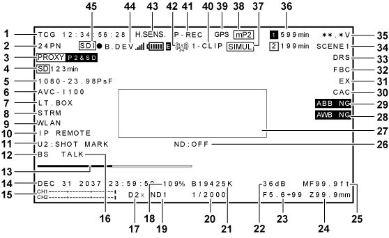
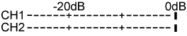
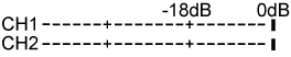
Audio level meter display
Switches between level meter display of audio output channels 1/2 and 3/4 while holding down the USER button where [LEVEL METER] is assigned.
The peak display on right edge is displayed in red during peak over.
The standard level display will switch as follows depending on the main menu → [AUDIO SETUP] → [RECORDING CH SETTING] → [HEADROOM] setting.
When set to [20dB]
When set to [18dB]
Headset talk display
This is displayed when the main menu → [SYSTEM MODE] → [BS DIRECT MODE] is set to [ON], and when [TALK] is enabled by pressing the <USER2> button on the camera.
Digital zoom display
Displays the digital zoom ratio.
[D2×]: two times
[D4x]: four times
Y GET brightness display
In the Y GET mode, the image level in the frame displayed near the center of the screen is displayed as 0% to 109%.
ND filter display
Displays the selected ND filter.
When [ND−] is displayed, the <ND FILTER> dial is shifted to position out of <1> to <4>. Check the position of the <ND FILTER> dial.
Shutter speed display
Displays the shutter speed. When synchro scan is performed, the display shows the content set in the main menu → [SCENE FILE] → [SYNC SCAN TYPE] (time (minutes) or open angle image).
<WHITE BAL> switch position display
Displays the position currently selected. Also, the white balance operation is indicated when the automatic white balance is preset. In auto tracking white balance (white balance with automatic tracking) mode, [ATW] is indicated, and when auto tracking white balance mode is locked, [LOCK] is indicated.
Gain display
Displays the gain value of the image amplifier configured.
[AGC] is displayed when auto gain control is active.
Iris display
Displays the F value.
[NC] is displayed when a lens connector is not connected.
Zoom position display
Displays the zoom position from [Z000] (maximum wide angle) to [Z999] (maximum zoom). Note, however, that this item is not displayed in the case of lenses without a zoom position return even if it is set to be displayed.
When a serial lens is connected, the display unit can be changed in main menu → [DISPLAY SETUP] → [ZOOM/FOCUS].
Focus control information display
Displays the focus control information from [99] to [00]. This item is not displayed, when other than a serial lens is connected or a lens that has no return of focus control information is connected.
When a serial lens is connected, the display unit can be changed in main menu → [DISPLAY SETUP] → [ZOOM/FOCUS].
Recommended ND filter display
Displays the ND filter recommended for the current shooting conditions.
Displayed when the automatic white balance is abnormal during mode check.
Automatic black balance abnormal display
Displayed when the automatic black balance is abnormal during mode check.
Chromatic aberration compensation function display
Displayed when the chromatic aberration compensation function is active.
Lens extender display
Displayed when the lens extender is used.
Flash band compensation function display
Displayed when the flash band compensation function is activated.
Dynamic range stretcher function display
Displayed when the dynamic range stretcher function is working.
Scene file name display
Indicates the scene file name [F1:] to [F6:].
Battery charge level indicator
[.V]: Displays the battery charge level in 0.1 V unit.
[%]: Displays the charge level of batteries with charge level information in %.
[EMP]: Displayed when there is no charge level on batteries with charge level information or the level is at the near end setting value or below.
[MAX]: Displayed when batteries with charge level information are fully charged.
P2 card remaining free space
: This is the slot No. This is displayed in black and white inversion when the slot No. is recording destination. It flashes while the card is being recognized.
[min]: Displays the remaining space on the media in each slot. During a near end, it flashes. 0 to 599 indicates minutes, while 600 minutes or longer indicates hours.
No display: Not displayed when a card is not inserted.
[END]: Displayed when there is no space remaining on each card.
[WP]: Displayed when the P2 card is write-protected.
[ERR]: Displayed in case of format errors or authentication errors.
[LOOP min]: Displayed when the loop recording mode is set. [LOOP] flashes when loop recording is not possible, for example, when there is no more space remaining on the P2 card. During the mode check, the second line displays the standard recording time of loop recording.
Simultaneous recording mode display
[SIMUL]: Displayed when the simultaneous recording is set. When the simultaneous recording cannot be performed, [SIMUL] indication is displayed with a diagonal line.
Recording media display
Among P2 and microP2 memory card slots, displays the slot that can perform recording and playback operations set in the main menu → [RECORDING SETUP] → [REC MEDIA].
[mP2]: microP2 memory card slot
[P2]: P2 memory card slot
GPS display
Displayed when the main menu → [OTHER FUNCTIONS] → [GPS] is set to [EXTERNAL].
The strength of signal reception is not displayed.
One clip recording mode status display
[1-CLIP]: The status where a new clip is to be recorded in one-clip recording
[1CLIP]: The status where recording can be performed by combining to the previous clip in one-clip recording
[CLIP] ([CLIP]): Clip forwarding (clip rewinding), cueing up by clips
[CLIP&T] ([CLIP&T]): Cueing up (rewinding) by clip and text memo (when [CLIP&TEXT MEMO] is set in the main menu → [OTHER FUNCTIONS] → [SEEK POS SEL])
[START]*1: Displayed when recording of a new clip is started in one-clip recording.
[END]*1: Displayed when combining of clips is ended in one-clip recording.
[L-]*2: Loop recording
[I-]*2: Interval recording, one-shot recording
[P-]*2: Pre-recording
Even if the display is set to [OFF], only [REC], [START], and [END] are displayed. Also, when pre-recording, loop recording, interval recording, or one-shot recording is set, it is displayed.
Displayed when [INTERVAL], [ONE SHOT], or [LOOP] is set in the main menu → [RECORDING SETUP] → [RECORDING], or when [ON] is set in the main menu → [RECORDING SETUP] → [PRE REC].
Rec during upload status and streaming distribution status display
Displays the status of rec during upload.
[]: Displayed when the rec during upload function is enabled.
The display will blink when recording is started immediately after the power is turned on or the P2 card is inserted, and the upload will not be performed until the recording is stopped.
[]: Displayed during upload.
[]: Displayed from when transfer error occurred during upload until when the next upload starts.
Displays the streaming status.
[] (blinking): Blinks while the camera is being connected to a device which will receive the streaming video.
[] (illuminated): Displayed when the camera is connected to a device receiving the streaming video and the camera is transmitting streaming video.
The display turns off when a connection could not be established properly.
High-sensitivity mode display
Displayed when [HIGH SENS.] is set in the main menu → [SYSTEM MODE] → [SHOOTING MODE].
4G/LTE connection status and the bonding device status display
Displays the 4G/LTE connection status. Displays at the 4G/LTE connection. Displays the strength of the signal reception in six levels. Displays the radio wave strength with the number of vertical bars. It is not displayed when the setting of 4G/LTE is disabled.
[4G/LTE]: During 4G/LTE connection
[4G/LTE]: When not connected with4G/LTE
[4G/LTE]: When there is a problem with the 4G/LTE connection
Displays the bonding device status. Displays the device status received from the bonding device. Displays the strength of the signal reception of the bonding device in six levels, and remaining battery in six levels. [E] is displayed when there is an error in the bonding device.
HD SDI REMOTE recording status display
Displays the control status of whether recording has started or stopped for an external device which is connected to the <SDI OUT1> terminal.
When [ON] is set in the main menu → [IN/OUT SEL] → [HD SDI REMOTE], the status will always be displayed regardless of the setting in the main menu → [DISPLAY SETUP].
[SDI]: Status where the recording is being instructed for an external device
[SDI]: Status where recording stop is being instructed for an external device
Camera status display
These are indicated in the information display area in the center.
[ABB]: Displayed while automatic black balance operation is active.
[ATW MODE]: Displayed when the <AUTO W/B BAL> switch is pushed to the <AWB> side while auto tracking white balance is active. This is also displayed when the <WHITE BAL> switch is turned to <B> if [ATW] is allocated.
[AWB]: Displayed while automatic white balance operation is active.
[WHITE:PRE K]: Displays the set color temperature when the <WHITE BAL> switch is switched.
[AWB PRESET K]: Displayed when the <WHITE BAL> was set to <PRST> in an attempt to execute automatic white balancing.
[BACK LIGHT]: Displayed when pressing the USER button to which [BACKLIGHT] is allocated for iris control, and switching the status.
[GAINdB]: Displayed when gain is switched.
[SHUTTER 1/]/[SHUTTER OFF]: Displayed when you switch the shutter speed.
[SPOT LIGHT]: Displayed when pressing the USER button to which [SPOTLIGHT] is allocated for iris control, and switching the status.
 ]: When the streaming mode is set but cannot operate due to other setting condition
 ]: When the wireless LAN is not connected (unlinked state)
 : This is the slot No. This is displayed in black and white inversion when the slot No. is recording destination. It flashes while the card is being recognized.
 ]: Playback pause
 ]: Playback
 ] ([
] ([ ]): Fast-forwarding/fast-forward playback (fast-reversing/fast-reverse playback)
 ]: Displayed when the rec during upload function is enabled.
 ]: Displayed during upload.
 ]: Displayed from when transfer error occurred during upload until when the next upload starts.
 ] (blinking): Blinks while the camera is being connected to a device which will receive the streaming video.
 ]: During 4G/LTE connection
 ]: When not connected with4G/LTE
 ]: When there is a problem with the 4G/LTE connection
 ]: Status where the recording is being instructed for an external device