- Top
- Parts and their functions
- Front panel 1
Front panel 1

|
1 |
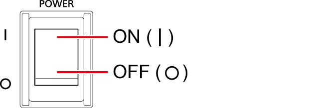
This is the unit’s power switch. Move it to the ON position to turn on the power.
|
||
|
2 |
This lights when [POWER] switch is set to ON and power is supplied to the unit. |
||
|
3 |
When you press the [CAMERA POWER] button, the unit begins supplying power to the camera. The color in which the button lights varies depending on the status of the camera. Status displays |
||
|
When the [CABLE CONNECTION] menu item is set to [HYBRID] |
|||
|
Lit (green) |
When the camera's power is ON, and communication between the camera and CCU is possible |
||
|
Lit (red) |
When camera was turned OFF on the camera side during standby power supply |
||
|
Flashing (red) |
When the camera can be turned ON from the unit or ROP during standby power supply |
||
|
Off |
When power is not supplied to the camera (e.g., [CABLE OPEN] status) |
||
|
When the [CABLE CONNECTION] menu item is set to [FIBER] |
|||
|
Lit (green) |
When communication between the camera and CCU is possible |
||
|
Off |
When communication between the camera and CCU is not possible |
||
|
4 |
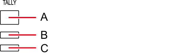
The lamp remains lit while tally signals (R, G, YL) are input.
A.R tally lamp B.G tally lamp C.YL tally lamp |
||
|
5 |
This connector is for connecting the intercom. This connector enables calls with the intercom line of the camera. Calls can also be made with the camera when the camera’s power is OFF. |
||
|
6 |
Indicates the camera number that has been assigned to the unit. |
||
|
7 |
Indicates the reception strength of optical transmission.
Indicates the reception strength on the camera side.
Indicates the reception strength on the CCU side. |
||