- Top
- Parts and their functions
- Rear panel 1
Rear panel 1

|
1 |
UHD (connects to the AK-UC4000), HS and 3G-HD, HD video signal output connectors (BNC). Signals output can be selected from the CCU menu. |
|
|
2 |
These connectors (BNC) are for outputting SDI signals in HDTV format. The 3G-HD/HD output mode can be selected by setting the CCU menu. SDI output from the [8/PM] connector can be switched to main line image output or picture monitor output via the CCU menu configurations or ROP control. |
|
|
3 |
This connector (BNC) is for outputting analog composite signals in SDTV format. The output from [VBS PM OUT] connector can be switched between output for this unit and output for the picture monitor via the CCU menu configurations. This unit's analog composite signal is for use with a monitor. Frame sequence locking is not applied to the BB (black burst) synchronization signal. |
|
|
4 |
This connector (BNC) is for inputting analog composite signals for return images in SDTV format. |
|
|
5 |
These connectors (BNC) are for inputting HD-SDI prompter signals. An active through signal is output from the [HD SDI PROMPT OUT] connector. |
|
|
6 |
This connector outputs the HD SDI TRUNK signal input or TICO to the camera. |
|
|
7 |
These connectors (BNC) are for inputting SDI signals for return images in HDTV and SDTV formats. 3G, HD-SDI, and SD-SDI signals are detected automatically. The signal input to [RET1 IN] connector is output from the [RET1 OUT] connector as an active through signal. |
|
|
8 |
This connector (BNC) is for inputting SD analog composite signals for the prompter. It is not terminated when the unit is turned OFF. You can switch between "output connector for the signal input to IN" or "input connector for ANALOG PROMPT2" for the [ANALOG PROMPT2 IN/OUT] connector via menu configurations. However, the signal is not output when the unit is turned OFF. |
|
|
9 |
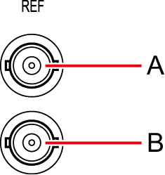
These connectors (BNC) are for inputting reference signals. Black burst (BB) signals and tri-level sync signals can be input, and the type of signals input is recognized automatically.*1 When no cable is connected to the loop-through output connector (B), the connector is automatically terminated at 75 Ω. Connecting a cable to this connector releases 75 Ω termination. When a cable is connected to the loop-through output connector (B), be sure to connect the other end of the cable to a connector.
A.Reference signal input connector B.Loop-through output When the [CCU MODE] is [1080/23.98psF], input 1080/23.98psF (47.95 Hz) tri-level sync signals. For details on supported sync signals for each format, see "Front panel [G/L ON] indicator specifications." |
|
|
10 |
LAN communication is carried using optical transmission between the camera and CCU. |