- Top
- CCU menu
- MAINTENANCE
- SETUP
SETUP
This is the selection screen for the SETUP menu.
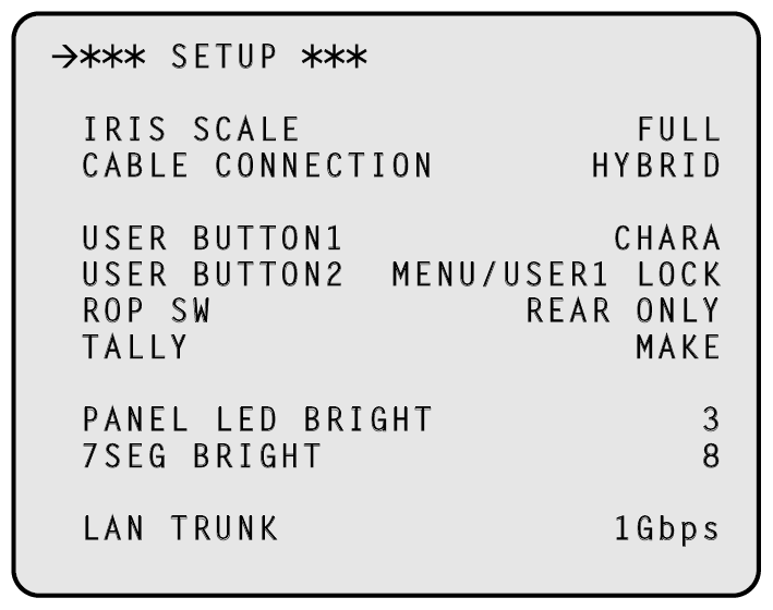
___ indicates factory default settings.
|
Item |
Setting value |
Setting details |
|---|---|---|
|
IRIS SCALE |
FULL 2STOP |
Set the IRIS display range of the status display screen. |
|
CABLE CONNECTION |
HYBRID FIBER |
Sets the cable used to connect the camera. HYBRID Select this when connecting the camera using an optical fiber multi cable. FIBER Select this when connecting the camera using only optical fiber. When [FIBER] is selected, power will not be supplied to the camera. In addition, the "OPEN" and "SHORT" errors will not be displayed. |
|
USER BUTTON1 |
NONE CHARA BARS CLEAN |
Set the function to be assigned to the [USER1] button on the front panel. NONE No assignment CHARA Character display, operation BARS Color bar ON/OFF CLEAN PM/NORM selection for SDI8 OUT |
|
USER BUTTON2 |
NONE CHARA MENU/USER1 LOCK BARS CLEAN |
Set the function to be assigned to the [USER2] button on the front panel. NONE No assignment CHARA Character display, operation MENU/USER1 LOCK Invalidate [MENU] button, [USER1] button (Function is assigned, but nothing happens when button pressed.) BARS Color bar ON/OFF CLEAN PM/NORM selection for SDI8 OUT |
|
FRONT ONLY REAR ONLY SWITCH SELECT |
Sets the connector used to connect ROP. FRONT ONLY Allows connection via the front panel only, regardless of the switch. REAR ONLY Allows connection via the rear panel only, regardless of the switch. SWITCH SELECT The setting will be determined by the front panel switch setting. |
|
|
TALLY |
MAKE V |
Select the input format for the TALLY signal. MAKE When the circuit between the TALLY IN H terminal and TALLY IN C terminal is OPEN, TALLY is OFF, and when it is MAKE, TALLY is ON.
V When voltage is applied to the TALLY IN H terminal, TALLY is ON, and when voltage is not applied, TALLY is OFF. Connect TALLY IN C to GND.
|
|
PANEL LED BRIGHT |
1 to 3 to 5 |
Sets the brightness of the front panel indicators. |
|
7SEG BRIGHT |
1 to 8 to 15 |
Sets the brightness of the 7-segment indicators. |
|
LAN TRUNK |
1Gbps 100Mbps |
Sets the communication speed for when LAN TRUNK is used. |