- Top
- Reference
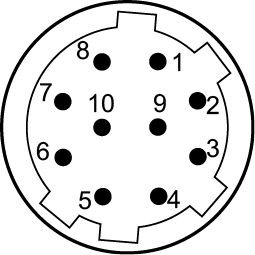
- Connector pin assignment table
- Rear panel
Rear panel
[AUX] connector
JAY-15S-1A3F(LF)(SN) (J.S.T. Mfg. Co., Ltd.)
|
Pin No. |
Function |
Specifications |
Remarks |
|---|---|---|---|
|
1 |
TALLY YL OUT |
Open collector output |
|
|
2 |
P6 |
See remarks |
When [AUX] > [FUNCTION] is set to [WFM_TYPE-A+SD_ASPECT] or [WFM_TYPE-B+SD_ASPECT] in the [MAINTENANCE] menu:
When [AUX] > [FUNCTION] is set to [AUDIO GAIN+SD_ASPECT] in the [MAINTENANCE] menu:
|
|
3 |
P5 |
||
|
4 |
P4 |
||
|
5 |
P3 |
||
|
6 |
P2 |
||
|
7 |
P1 |
||
|
8 |
GND |
Ground |
|
|
9 |
MODE2 |
Photo-coupler input |
|
|
10 |
MODE1 |
Photo-coupler input |
|
|
11 |
GND |
Ground |
|
|
12 |
ALARM |
Open collector output |
|
|
13 |
TALLY R OUT |
Open collector output |
|
|
14 |
TALLY G OUT |
Open collector output |
|
|
15 |
GND |
Ground |


Down-conversion mode settings
|
Down-conversion mode |
MODE1 |
MODE2 |
|---|---|---|
|
Local |
Open |
Open |
|
Letter box |
Shorted |
Open |
|
Squeeze |
Open |
Shorted |
|
Side panel |
Shorted |
Shorted |
Shorted: Shorted with pin 8 (GND)
Preset settings of waveform monitor
|
TYPE-A |
AUX connector output |
|||||
|---|---|---|---|---|---|---|
|
P6 |
P5 |
P4 |
P3 |
P2 |
P1 |
|
|
PRESET1 |
Shorted |
Shorted |
Shorted |
Shorted |
Shorted |
Open |
|
PRESET2 |
Shorted |
Shorted |
Shorted |
Shorted |
Open |
Shorted |
|
PRESET3 |
Shorted |
Shorted |
Shorted |
Shorted |
Open |
Open |
|
PRESET4 |
Shorted |
Shorted |
Shorted |
Open |
Shorted |
Shorted |
|
PRESET5 |
Shorted |
Shorted |
Shorted |
Open |
Shorted |
Open |
|
PRESET6 |
Shorted |
Shorted |
Shorted |
Open |
Open |
Shorted |
|
TYPE-B |
AUX connector output |
|||||
|---|---|---|---|---|---|---|
|
P6 |
P5 |
P4 |
P3 |
P2 |
P1 |
|
|
PRESET1 |
Open |
Open |
Open |
Open |
Open |
Shorted |
|
PRESET2 |
Open |
Open |
Open |
Open |
Shorted |
Open |
|
PRESET3 |
Open |
Open |
Open |
Shorted |
Open |
Open |
|
PRESET4 |
Open |
Open |
Shorted |
Open |
Open |
Open |
|
PRESET5 |
Open |
Shorted |
Open |
Open |
Open |
Open |
|
PRESET6 |
Shorted |
Open |
Open |
Open |
Open |
Open |
Shorted: Shorted with pin 8 (GND)
AUDIO GAIN settings
You can control camera microphone gain from an external device.
|
Gain control setting |
P1 |
P2 |
|---|---|---|
|
Disabled |
Open |
Open |
|
MIC1 enabled |
Shorted |
Open |
|
MIC2 enabled |
Open |
Shorted |
|
MIC1 and MIC2 enabled |
Shorted |
Shorted |
|
Camera microphone gain setting |
Total gain |
P3 |
P4 |
P5 |
|
|---|---|---|---|---|---|
|
MIC GAIN |
AMP |
||||
|
60 |
0 |
60 dB |
Open |
Open |
Open |
|
40 |
10 |
50 dB |
Shorted |
Open |
Open |
|
40 |
0 |
40 dB |
Open |
Shorted |
Open |
|
20 |
10 |
30 dB |
Shorted |
Shorted |
Open |
|
20 |
0 |
20 dB |
Open |
Open |
Shorted |
Shorted: Shorted with pin 8 (GND)
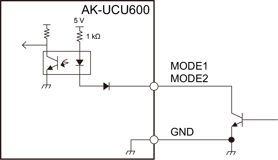
Example of mode input connections
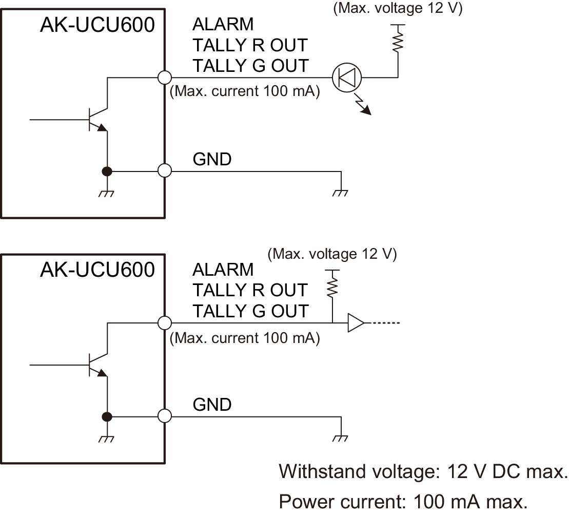
Example of tally and alarm output connections
[TRUNK] connector
JEY-9S-1A3F (LF)(SN) (J.S.T. Mfg. Co., Ltd.)
|
Pin No. |
Function |
Flow of signal |
Remarks |
|---|---|---|---|
|
1 |
TRUNK1_TX (C) |
CAM → CCU |
|
|
2 |
TRUNK1_TX (H) |
CAM → CCU |
|
|
3 |
TRUNK1_RX (H) |
CCU → CAM |
|
|
4 |
TRUNK1_RX (C) |
CCU → CAM |
|
|
5 |
GND |
||
|
6 |
TRUNK2_TX (C) |
CAM → CCU |
|
|
7 |
TRUNK2_TX (H) |
CAM → CCU |
|
|
8 |
TRUNK2_RX (H) |
CCU → CAM |
|
|
9 |
TRUNK2_RX (C) |
CCU → CAM |
[COMMUNICATION] connector
JBY-25S-1A3F(LF)(SN) (J.S.T. Mfg. Co., Ltd.)
|
Pin No. |
Function |
Flow of signal |
Remarks |
|---|---|---|---|
|
1 |
INCOM ENG OUT (H) |
CCU→SYSTEM |
0 dBm, 600 Ω (4 W) / 1 V [p-p], 200 Ω (RTS) 4 W/RTS/CLRCOM
|
|
2 |
INCOM ENG OUT (C) |
CCU→SYSTEM |
|
|
3 |
INCOM ENG (GND) |
||
|
4 |
INCOM ENG IN (H) |
SYSTEM→CCU |
|
|
5 |
INCOM ENG IN (C) |
SYSTEM→CCU |
|
|
6 |
PGM IN (H) |
SYSTEM→CCU |
0 dBm/-20 dBm, 600 Ω
|
|
7 |
PGM IN (C) |
SYSTEM→CCU |
|
|
8 |
PGM IN (GND) |
||
|
9 |
GND |
||
|
10 |
NC |
||
|
11 |
R TALLY IN (H) |
SYSTEM→CCU |
ON: Short/TTL(H)/24 V
OFF: Open/TTL(L)/0 V |
|
12 |
R TALLY IN (C) |
SYSTEM→CCU |
|
|
13 |
GND |
||
|
14 |
INCOM PROD OUT (H) |
CCU→SYSTEM |
0 dBm, 600 Ω (4 W) / 1 V [p-p], 200 Ω (RTS) 4 W/RTS/CLRCOM
|
|
15 |
INCOM PROD OUT (C) |
CCU→SYSTEM |
|
|
16 |
INCOM PROD (GND) |
||
|
17 |
INCOM PROD IN (H) |
SYSTEM→CCU |
|
|
18 |
INCOM PROD IN (C) |
SYSTEM→CCU |
|
|
19 |
PGM2 IN (H) |
SYSTEM→CCU |
0 dBm/-20 dBm, 600 Ω
|
|
20 |
PGM2 IN (C) |
SYSTEM→CCU |
|
|
21 |
PGM2 IN (GND) |
||
|
22 |
YL TALLY IN (H) |
SYSTEM→CCU |
ON: Short/TTL(H)/24 V
OFF: Open/TTL(L)/0 V |
|
23 |
YL TALLY IN (C) |
SYSTEM→CCU |
|
|
24 |
G TALLY IN (H) |
SYSTEM→CCU |
|
|
25 |
G TALLY IN (C) |
SYSTEM→CCU |


Example of tally input connections
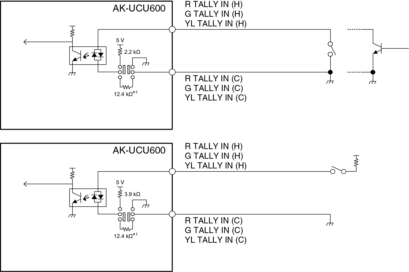
Equivalent circuit
[ROP] connector
HR10G-10R-10SC (71) (Hirose Electric Co., Ltd.)
|
Pin No. |
Function |
Flow of signal |
|---|---|---|
|
1 |
ROP CONT (H) |
CCU→ROP |
|
2 |
ROP CONT (C) |
CCU→ROP |
|
3 |
ROP DATA (H) |
ROP→CCU |
|
4 |
ROP DATA (C) |
ROP→CCU |
|
5 |
NC |
|
|
6 |
NC |
|
|
7 |
NC |
|
|
8 |
NC |
|
|
9 |
+16 V OUT |
CCU→ROP |
|
10 |
GND |
- Connector of cable
HR10A-10P-10P (73)
[MSU] connector
HR10G-10R-10SC (71) (Hirose Electric Co., Ltd.)
|
Pin No. |
Function |
Flow of signal |
|---|---|---|
|
1 |
MSU CONT (H) |
CCU→MSU |
|
2 |
MSU CONT (C) |
CCU→MSU |
|
3 |
MSU DATA (H) |
MSU→CCU |
|
4 |
MSU DATA (C) |
MSU→CCU |
|
5 |
TALLY R |
CCU→MSU |
|
6 |
TALLY G |
CCU→MSU |
|
7 |
HEAD POWER |
CCU→MSU |
|
8 |
ALARM 1 |
CCU→MSU |
|
9 |
ALARM 0 |
CCU→MSU |
|
10 |
GND |
- Connector of cable
HR10A-10P-10P (73)

[MIC1] and [MIC2] connectors
HA16RV-3PG(76) (Hirose Electric Co., Ltd.)
|
Pin No. |
Function |
Flow of signal |
Remarks |
|---|---|---|---|
|
1 |
SHIELD |
0 dBm, 600 Ω |
|
|
2 |
HOT |
CCU→SYSTEM |
|
|
3 |
COLD |
CCU→SYSTEM |
- When connecting to an unbalanced input terminal of an external device, connect to it as shown in the diagram below.
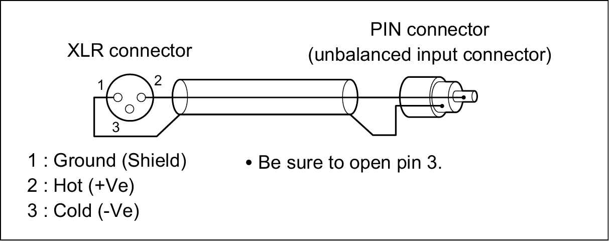
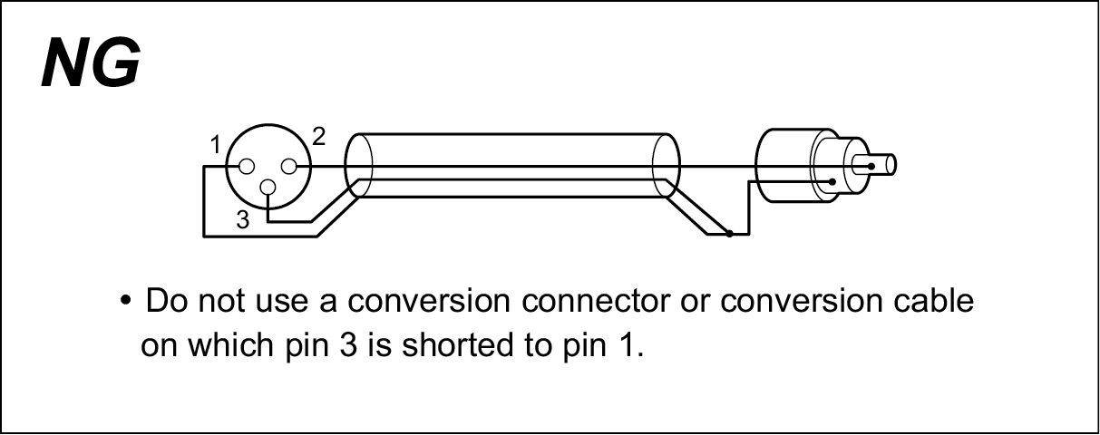
- Some commercially available conversion connectors and conversion cables have pin 3 shorted to pin 1.
Using such a conversion connector or conversion cable will cause a failure.
[CAMERA] connector
AK-UCU600: OPS2404-PR (Tajimi Electronics Co., Ltd.)
AK-UCU600S: FXW.3K.93C.TLM (LEMO)
|
Pin No. |
Function |
Flow of signal |
|---|---|---|
|
1 |
Optical fiber |
CAM → CCU |
|
2 |
Optical fiber |
CCU → CAM |
|
3 |
Control line |
CCU←→CAM |
|
4 |
Control line |
CCU←→CAM |
|
5 |
AC 240 V |
CCU → CAM |
|
6 |
AC 240 V |
CCU → CAM |