- Top
- Description of Parts
- Camera
- Right side
Right side
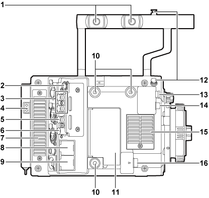
Accessory mounting holes
For attaching accessories.
Mounting hole size
3/8-16 UNC
<CONTROL PANEL> terminal
A terminal to connect the control panel.
<SDI OUT 1>/<SDI OUT 2> terminal
Output terminals of 3G/HD SDI for video monitor.
For the cable to connect to this terminal, prepare a double-shielded cable equivalent to 5C-FB.
Power supply output terminal for lighting
Power supply terminal when light is connected.
<GENLOCK IN> terminal
Inputs reference signals when setting the genlock on the camera unit or when externally locking the time code. Also, the video signal that is being input can be confirmed in the viewfinder, etc., while the button with [RETURN] assigned is pressed. The input signal is 3G/HD-SDI.
For the cable to connect to this terminal, prepare a double-shielded cable equivalent to 5C-FB.
<TC IN/OUT> terminal
Connects to the time code input terminal of the external device when locking the time code of the external device to the time code on the camera.
Inputs the standard time code when locking with the time code of the external device.
For the cable to connect to this terminal, prepare a double-shielded cable equivalent to 5C-FB.
Fan outlet
Fan outlet for dissipating heat. Do not block this when the camera is in use.
<LAN> terminal
For connecting a LAN (100BASE-TX) cable.
Use the shielded cross cable for the cable to connect to this terminal.
<USB DEVICE> terminal
USB device terminal for connecting a USB 2.0 cable.
For the cable to connect to this terminal, prepare a double-shielded cable.
Accessory mounting holes
For attaching accessories.
Mounting hole size
1/4-20 UNC (screw length 5.5 mm or shorter)
<USB HOST> terminal (inside the cover, 5.0 V 0.5 A max)
For mounting the wireless module AJ-WM30/AJ-WM50 (optional).
For the cable to connect to this terminal, prepare a double-shielded cable.
Focus hook
Indicates the image surface plane of the image sensor. Use this mark as a reference to measure the exact distance from the subject.
<VF SDI> terminal
An output terminal of 3G/HD SDI for connecting the viewfinder.
Use the BNC cable supplied with the viewfinder or the double-shielded cable equivalent to 5C-FB when connecting a cable to this terminal.
<DC OUT> terminal (Connecting to the <DC OUT> terminal)
An output terminal to supply viewfinder power supply DC 12 V. Maximum of 1.0 A current can be provided.
Use the DC cable supplied with the viewfinder when connecting a cable to this terminal.
Fan inlet
Fan inlet for dissipating heat. Do not block this when the camera is in use.
<LENS/GRIP> terminal
Terminal for connecting a lens cable. For details, refer to the Operating Instructions for the lens.
Cable for the grip module AU-VGRP1G (optional) can also be connected.