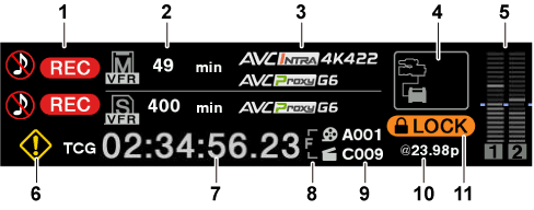
 : When audio is not being recorded
 : Warning (details are displayed on the time code display in the following cases)
 : Alert
 (White): Operating but not connected.
 (Yellow): Operating. A device is connected.
 (Red): An error has occurred.
 (Gray): No compatible device.
 (White): Operating but not connected.
 (Yellow): Operating. A device is connected.
 (Red): An error has occurred.
 (Gray): No compatible device.
 (White): Operating but not connected.
 (Yellow): Operating. A device is connected.
 (Red): An error has occurred.
Power supply display
Displays the connection status and remaining capacity of the battery and external power supply.
The remaining capacity information is displayed in “%” if there is any. It is displayed as voltage “V” if % display is not possible.
Displays [EMP] in red character when the end is reached, and [LOW] in yellow character when the near end is reached.
Select [DC POWER SUPPLY] or [BATTERY] to match the power supply to connect in [MENU] → [SYSTEM SETTINGS] → [POWER MANAGEMENT] → [DC IN SOURCE] when connecting an external power supply to the <DC IN> terminal.
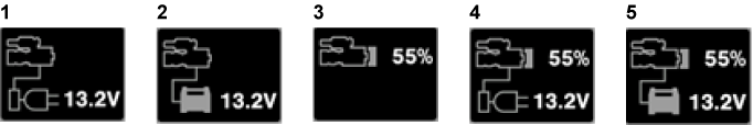
<DC IN> power supply display
This is the display when an AC adaptor ([DC POWER SUPPLY]) is connected to the <DC IN> terminal.
<DC IN> power supply display
This is the display when a battery is connected to the <DC IN> terminal.
Battery display
This is the display when a battery is connected to the battery holder.
Battery and <DC IN> power supply display
This is the display when a battery is connected to the battery holder and an AC adaptor ([DC POWER SUPPLY]) is connected to the <DC IN> terminal.
Battery and <DC IN> power supply display
This is the display when a battery is connected to the battery holder and a battery is connected to the <DC IN> terminal.