- Top
- Description of Parts
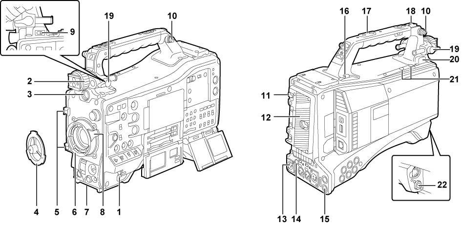
- Power supply and accessory mounting section
Power supply and accessory mounting section
<POWER> switch (Power supply setup to P2 card insertion)
Turn the power to on/standby.
To turn on, set the power switch to <
 > (ON). To set to standby, set the power switch to <
  > (standby).
Viewfinder left/right positioning ring
To adjust the left/right position of the viewfinder, loosen this ring, and slide the viewfinder to the left or right to adjust it to an easy-to-view position. After adjustment, turn in the <LOCK> direction and firmly clamp.
<VF> terminal
Mount the viewfinder AG-CVF15G (optional), AJ-CVF50G (optional), etc.
Mount cap (Mounting the lens)
Raise the lens lever to remove the cap. Replace the cap when the lens is not mounted.
Lens cable/microphone cable clamp (Mounting the lens)
Used for securing the lens and microphone cables.
Lens mount (2/3-type bayonet) (Mounting the lens)
Mount the lens.
Tripod mount (Mounting the camera on a tripod)
Attach the optional tripod adaptor (SHAN-TM700) when mounting the camera on the tripod.
Lens lever (Mounting the lens)
After mounting the lens to the lens mount, tighten the lever to secure the lens.
<LIGHT> switch
Select how to turn on/off the video light connected to the light output terminal.
<AUTO>
When the video light is left turned on, the light is illuminated at the same time that recording starts on the camera and goes out at the same time that recording stops.
<MANUAL>
The light is illuminated according to whether the video light is turned on/off.
Shoulder strap fittings (Attaching the shoulder strap)
Attach the shoulder strap.
Battery release lever (Mounting and setting battery)
Pull this battery release lever down to release the battery.
Battery holder (Mounting and setting battery)
Mount the Anton/Bauer battery.
<DC IN> terminal (Using external DC power supply)
This is the input terminal for the external power supply. Connect to the external DC power supply.
<DC OUT> (DC power supply) output terminal (Connecting the <DC OUT> terminal with the external recording start/stop switch)
This is the DC12 V output terminal. It provides a maximum current of 1.5 A.
<REMOTE> terminal (Connecting to the extension control unit (AG-EC4G)) (Connecting to Remote operation panel (AK-HRP200G))
Connect the extension control unit AG-EC4G (optional) to remote-control some functions. For details, refer to “Connecting to the extension control unit (AG-EC4G)”.
Connect the remote operation panel AK-HRP200G (optional) to remote-control some functions. For details, refer to “Connecting to Remote operation panel (AK-HRP200G)”.
Cable holders
Used for clamping the light and microphone cables in place.
Accessory mounting holes
Attach accessories. Do not use for purposes other than attaching accessories.
Mounting hole size
1/4-20 UNC (screw length 10 mm or shorter)
3/8-16 UNC (screw length 10 mm or shorter)
Light shoe
Attach the video light.
Mounting hole size
1/4-20 UNC (screw length 6 mm or shorter)
Viewfinder front/back position clamp lever
To adjust the front/back position of the viewfinder, loosen this lever, and slide the viewfinder to the left or right to adjust it to an easy-to-view position. After adjustment, turn in the <LOCK> direction and firmly clamp.
Light output terminal
Connect the Ultralight 2 of Anton/Bauer (optional) or an equivalent video light of 50 W or under.
The battery charge level drops sharply when the light is illuminated. When using the light, using a battery of 90 Wh or more is recommended.
Microphone holder mounting screws
Screws for mounting the microphone holder AJ-MH800G (optional) or VF interface box AG-YA500G (optional).
<LENS> terminal (Mounting the lens)
Connect the lens connection cable. For details of the lens used, refer to the Operating Instructions for the lens.