- Top
- Description of Parts
- Shooting and recording/playback functions section
- Shooting and recording/playback functions section (Recording unit)
Shooting and recording/playback functions section (Recording unit)
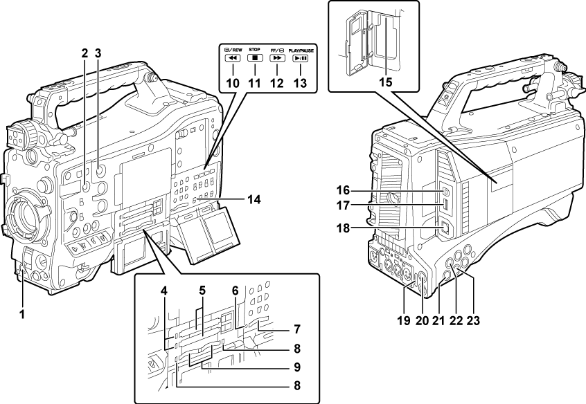
<REC> button (Standard recording)
Recording is started by pressing this button. Recording is stopped by pressing this button again.
This button has the same function as the VTR button on the lens side.
<SHOT MARKER> button (Shot mark recording function)
Shot marks can be added to the thumbnail of a clip while that clip is being recorded. Thumbnails can also be selected in the LCD monitor, and shot marks can be added by pressing this button.
The selected function can be assigned as the <USER3> button. Set the function to be assigned in the main menu → [CAMERA] → [USER SW] → [SHOT MARK (U3)].
<TEXT MEMO> button (Text memo recording function)
Text memos can be recorded by pressing this button during recording/playback or while playback is paused.
The selected function can be assigned as the <USER4> button. Set the function to be assigned in the main menu → [CAMERA] → [USER SW] → [TEXT MEMO (U4)].
P2 memory card access LED (P2 card access LEDs and status of P2 cards)
Indicate the access status of recording and playback of each card.
P2 memory card slot
Busy (active status indication) lamp (Removing SD memory cards)
Indicate the active status of the SD memory card, and is illuminated when the card is active.
SD memory card slot (Inserting SD memory cards)
This is the insertion slot for the SD memory card (optional). Use the SD memory card for recording/opening the setting menu and lens files for the camera, or uploading metadata or proxy recording, etc.
microP2 memory card access LED (P2 card access LEDs and status of P2 cards)
Indicates the access status of recording and playback of each microP2 memory card.
microP2 memory card slot
<
 /REW> (rewind) button
Press this button during a pause to perform fast-reverse playback.
Press it during playback to perform fast-reverse playback at approximately 4x speed.
If it is pressed with playback paused, the clip being played back is paused at its start point (cued state).
<STOP> (stop) button
Press this button to stop playback. Press it to stop interval recording or one-shot recording, or to end linking of clips in one-clip recording.
<FF/
 > (fast forward) button
Press this button during a pause to perform fast playback.
Press it during playback to perform fast playback at approximately 4x speed.
If it is pressed with playback paused, the clip being played back is paused at the start point of the next clip (cued state).
<PLAY/PAUSE> (play/pause) button
Press this button to view the playback image using the viewfinder screen or the monitor screen.
Pressing it during playback pauses playback.
<MON OUT CHARACTER> switch (Superimposing the time code)
Specifies whether characters are superimposed over the images output from <SDI OUT2>, <VIDEO OUT>, and <HDMI OUT> terminals.
<ON>
Superimposes characters.
<OFF>
Does not superimpose characters.
<USB2.0> terminal (sub-host)
Mount the wireless module AJ-WM30/AJ-WM50 (optional).
<USB2.0> terminal (device) (Connecting to a computer in the USB device mode)
In the USB device mode, the camera can be connected to the computer by the USB 2.0 cable to transfer data. In this case, recording playback operations and camera shooting are not possible.
<USB3.0> terminal (host) (USB storage mode)
In the USB storage mode, connect external hard disk drives, etc.
<LAN> terminal (100BASE-TX)
Connect a LAN cable.
<HDMI OUT> (monitor output) terminal
This is the video output terminal for the monitor. Video can be output separately from the <SDI OUT1> terminal according to the setting of the main menu → [I/F SETUP] → [OUTPUT SEL] → [MONITOR OUT MODE]. The down-conversion signal can be selected in [OUTPUT SEL] → [SDI2/HDMI OUT]. Up-conversion is not supported.
Superimposing of characters can be set by the <MON OUT CHARACTER> switch independently of the <SDI OUT1> terminal. (Superimposing the time code)
<SDI OUT1> (output) terminal
This is the output terminal exclusively for SDI. Output is performed in the same signal format as in the system mode. Down-conversion and up-conversion are not supported.
Superimposing of characters can be set independently of the <HDMI OUT>, <SDI OUT2>, and <VIDEO OUT> terminals. (Superimposing the time code)
<SDI OUT2> (monitor output) terminal
This is the video output terminal for the monitor. Video can be output separately from the <SDI OUT1> terminal according to the setting of the main menu → [I/F SETUP] → [OUTPUT SEL] → [MONITOR OUT MODE]. HD SDI or down-converted SD SDI can be selected in [OUTPUT SEL] → [SDI2/HDMI OUT]. Up-conversion is not supported.
Superimposing of characters can be set by the <MON OUT CHARACTER> switch independently of the <SDI OUT1> terminal. (Superimposing the time code)
<SDI IN> (input) terminal
Input the HD/SD SDI signals. Signals from this input terminal can be recorded by setting [SDI] in the main menu → [SYSTEM] → [SYSTEM MODE] → [REC SIGNAL]. 3G-SDI input signals can be recorded at 1080P. For details, refer to “Selecting recording signals”.
In the main menu → [I/F SETUP] → [GENLOCK] → [GENLOCK] → [SDI IN], a generator lock can also be applied referenced to this input signal. (Generator-locking to the reference signal supplied from the <SDI IN> terminal)
<VIDEO OUT> (monitor output) terminal
This is the video output terminal for the monitor. Video can be output separately from the <SDI OUT1> terminal according to the setting of main menu → [I/F SETUP] → [OUTPUT SEL] → [MONITOR OUT MODE]. The VBS signal is output at all times.
Superimposing of characters can be set by the <MON OUT CHARACTER> switch independently of the <SDI OUT1> terminal. (Superimposing the time code)