- Top
- Shooting
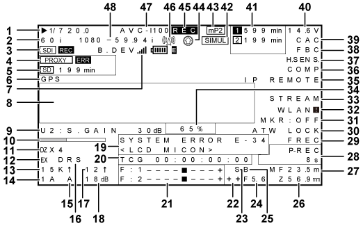
- Viewfinder status display
- Screen display
Screen display
Shutter speed/mode
[
 1/
1/ .]
.]The shutter speed is set to synchro scan.
[1/60 (1/100)] - [1/2000], [HALF], [
.d]A fixed shutter speed is set.
Camera mode
Displays the video method when the signals output from the MOS sensor are recorded to the P2 card or output as video signals.
[60P]
1080/59.94P or 720/59.94P
[60i]
1080/59.94i or 480/59.94i
[50P]
1080/50P or 720/50P
[50i]
1080/50i or 576/50i
[30P]
1080/29.97P or 720/29.97P
[24P]
1080/23.98P, 1080/23.98PsF or 720/23.98P
[25P]
1080/25P or 720/25P
HD SDI recording control information display
This is displayed when the recording control information is superimposed on the HD SDI signal output from the <SDI OUT1> or <SDI OUT2> terminal while [HDSDI REMOTE] in the main menu → [I/F SETUP] → [OUTPUT SEL] is set to [ON].
[SDI REC]
Recording instruction is being output.
[SDI
 ]
]Recording standby instruction is being output.
Proxy information display
Displays the proxy recording information.
[PROXY P2 (P2&SD)]
Displayed when proxy recording is started.
[PROXY ERR]
Displayed when there is an error in proxy recording.
SD memory card status display
[WP]
Write protect
[END]
No remaining free space
[WR ERR]
Write error
[SD
min]The remaining amount is displayed when proxy is recorded to SD memory card. (Displayed only in the regular mode check)
Flashing when the remaining capacity is one minute or less. [−−min] is displayed when there is no SD memory card.
External GPS display
This is displayed when the main menu → [SYSTEM] → [SYSTEM SETUP] → [GPS] is set to [EXTERNAL].
The strength of signal reception is not displayed.
4G/LTE connection status and the bonding device status display
Displays the 4G/LTE connection status.
Displays the following when connected to 4G/LTE. The signal reception strength is displayed in 6 levels. The number of vertical bars represent the signal strength. Not displayed when the 4G/LTE setting is disabled.
[4G/LTE
 ]
]Displayed when connected to 4G/LTE.
[4G/LTE
 ]
]Displayed when not connected to 4G/LTE.
[4G/LTE
 ]
]Displayed when there is an error in the 4G/LTE connection.
Displays the bonding device status. Displays the device status received from the bonding device. The strength of the signal reception is displayed in 6 levels, and remaining battery is displayed in 6 levels. [E] is displayed when there is an error in the bonding device.
Camera warning, notification display area
(Related to automatic white balance, automatic black balance and switch operation)
[AWB A ACTIVE]
Displayed when automatic white balance is active on the <A> channel.
[AWB B ACTIVE]
Displayed when automatic white balance is active on the <B> channel.
[AWB A OK
.K]Displayed when automatic white balance has ended successfully on the <A> channel.
[AWB B OK
.K]Displayed when automatic white balance has ended successfully on the <B> channel.
[AWB BREAK
.K]Displayed when automatic white balance operation is forcibly ended.
[AWB NG]
Displayed when automatic white balance operation is not ended successfully. The 2nd line displays that status.
[COLOR TEMP LOW]
Warns that the color temperature is too low.
[COLOR TEMP HIGH]
Warns that the color temperature is too high.
[LEVEL OVER]
Warns that the brightness is too high.
[LOW LIGHT]
Warns that the brightness is too low.
[TIME OVER]
Warns that processing could not be executed within the operation time.
[ATW MODE]
Displayed when automatic white balance cannot be executed due to activation of auto tracking white balance.
[AWB PRESET
.K]Displayed when the <WHITE BAL> switch is set to <PRST> and automatic white balance operation cannot be executed.
[AWB UNABLE]
Displayed when automatic white balance operation cannot be executed. The 2nd line displays that status.
[S.GAIN MODE]
Displayed when super gain is active.
[CHECK FILTER]
Prompts re-confirmation of the filter switching dial position when the power is turned on and automatic white balance is active.
[ABB ACTIVE]
Displayed when automatic black balance operation is active.
[ABB OK]
Displayed when automatic black balance operation is ended successfully.
[ABB BREAK]
Displayed when automatic black balance operation is forcibly ended.
[ABB NG]
Displayed when automatic black balance operation is not ended successfully.
[B-SHD READY]
Displayed when black shading operation is accepted by holding down the <AUTO W/B BAL> switch during automatic black balance operation.
[B-SHD ACTIVE]
Displayed when black shading operation is active.
[B-SHD OK]
Displayed when black shading operation is ended.
[B-SHD BREAK]
Displayed when black shading operation is forcibly ended.
[B-SHD NG]
Displayed when black shading operation is not ended successfully.
(Switch selection display)
[WHITE:#]
Displayed when the <WHITE BAL> switch is switched. One of [A]/[B]/[PRST] is displayed at [#].
[ATW MODE]
Displayed when automatic tracking white balance operation is set.
[
.K]Displays the currently set color temperature.
[AUTO KNEE:ON/OFF]
Displayed when the <OUTPUT>/<AUTO KNEE> selector switch where [ON] or [OFF] is assigned in the main menu → [CAMERA] → [SW MODE] → [AUTO KNEE SW] is set to <ON>/<OFF>.
[DRS:ON/OFF]
Displayed when the <OUTPUT>/<AUTO KNEE> selector switch where [DRS] is assigned in the main menu → [CAMERA] → [SW MODE] → [AUTO KNEE SW] is set to <ON>/<OFF>.
[GAIN:
dB+↑]Displayed when gain is switched by the <GAIN> switch or <USER> button. When digital super gain is active, that value is displayed at the same time.
[SS:1/
] or [.deg]When the shutter speed is switched, that value is displayed.
[SS:
1/] or [.d]Displayed when syncro scan is selected for the shutter speed.
[CC:
K]Displayed when the <CC FILTER> dial position is switched.
[ND:
]Displayed when the <ND FILTER> dial position is switched.
[EXTENDER:ON/OFF]
Displays the status of the lens extender.
[IRIS:
F.]Displayed when the iris override compensation value is altered.
(Drop in brightness warning display)
[LOW LIGHT]
Displayed when brightness has dropped.
(Flash band compensation warning display)
[FBC OFF!]
Displayed when a flash band is detected while flash band compensation is off.
[SHUTTER&FBC ON!]
Displayed when the <SHUTTER> switch is <ON> and flash band compensation is set to on.
<USER> button assignment information
[UM]
Indicates the <USER MAIN> button.
[U1]
Indicates the <USER1> button.
[U2]
Indicates the <USER2> button.
[U3]
Indicates the <SHOT MARK> button.
[U4]
Indicates the <TEXT MEMO> button.
[U5]
Indicates the <USER5> button.
[RET]
Indicates the <RET> button.
[INHIBIT]
Displayed when the <USER> button is not operated.
[S.GAIN
dB/OFF]Displays the selected super gain.
[DS.GAIN
↑/OFF]Displays the selected digital super gain.
[S.IRIS ON/OFF]
Displays the super iris operation status.
[I.OVR ON/OFF]
Displays the iris override operation status.
[S.BLK −
/OFF]Displays the super black operation status. During operation, the setting value is also displayed.
[B.GAMMA ON/OFF]
Displays the operation status of black gamma (black level tone compensation).
[D.ZOOM x2/x3/x4/OFF]
Displays the digital zoom factor.
[ATW ON/OFF]
Displays the operation status of automatic tracking white balance.
[ATW LOCK ON/OFF]
Displays the lock status of automatic tracking white balance operation.
[AUD CH1/3]
Displayed when the input signal to record to audio channel 1 or 3 is switched.
[AUD CH2/4]
Displayed when the input signal to record to audio channel 2 or 4 is switched.
[REC SW]
Displayed when the <USER> button is functioning as the <REC> switch.
[Y GET ON]
Displayed when the [Y GET] function is [ON].
[RET SW]
Displayed when the <USER> button is functioning as the <RET> switch.
[SLOT SEL]
Displayed when the switch for switching the card to record to is set.
[PRE REC]
Displayed when the pre-recording mode is switched.
[USB STORAGE/DEVICE/OFF]
Displayed when the USB operation status is switched.
[DRS ON/OFF]
Displays the operation status of the dynamic range stretcher.
[ASSIST ON/OFF]
Displays the focus assist operation status.
[C.TEMP ON/OFF]
Displays the status of the mode for changing the color temperature by the jog dial button.
[SHOT MARK]
Displayed when shot marks are added or deleted.
[TEXT MEMO]
Displayed when a text memo is recorded.
[WFM]
Displayed when the waveform monitor is switched.
[FBC ON/OFF]
Displays the operation status of the flash band compensation function.
[EVF CLR]
Displays the color status of the viewfinder.
[REC MEDIA]
Displayed when the slot of the media used for recording is switched to [P2] (P2 memory card slots 1/2) or [mP2] (microP2 memory card slots 3/4).
[CAM RET]
Displayed when the button assigned with the camera return function is pressed.
[REC CHECK]
Displayed when the button assigned with the recording check function is pressed.
[REC D. UP]
Displayed when enabling/disabling the rec during upload function.
[UP LIST]
Displayed when the button assigned to the function to display the upload list of the rec during upload function is pressed.
[STREAMING]
Displayed when starting/stopping streaming from the camera.
[V/L HLG ON/OFF]
Displayed when the monitoring gamma image of the viewfinder and LCD monitor is switched to a hybrid log gamma image.
Focus bar display
Displays the high-frequency component of the video after conversion to a graph at the bottom left of the viewfinder. For details, refer to “Focus assist function”.
Digital zoom ratio display
Displays the digital zoom factor.
[DZx2]
2 times
[DZx3]
3 times
[DZx4]
4 times
Extender
[EX]
Displayed when the lens extender is used.
Color temperature
[
.K]Displays the color temperature assigned to <A>, <B>, and <PRST> of the <WHITE BAL> switch. (This is sometimes a memory value at execution of automatic white balance and sometimes a menu setting value.)
Not displayed when auto tracking white balance is performed.
Filter position
[1] to [4]
Displays the position of the <ND FILTER> dial.
[A] to [D]
Displays the position of the <CC FILTER> dial.
[−] (flashing)
The filter position is not set to the specified position.
<WHITE BAL> switch position
[A]
The <WHITE BAL> switch is set to <A>.
[B]
The <WHITE BAL> switch is set to <B>.
[P]
The <WHITE BAL> switch is set to <PRST>.
[T]
The switch is set to [ATW]. Note, however, that this flashes when brightness and color are outside the operation range.
Dynamic range stretcher (DRS) function display
[DRS]
Displayed when the image level in high-brightness areas is compressed and the dynamic range is stretched.
Incremental gain display
Displays the value when incremental gain is functioning.
[6 ↑]/[10 ↑]/[12↑]/[15↑]/[20↑]/[24↑]/[28↑]/[34↑]
Gain display
Displays the gain value of the image amplifier configured.
[
dB]Displays the current gain value.
[AGC]
Displayed when auto gain control is active.
System information and warning
[SYSTEM ERROR E-
]Displayed when an abnormality in internal microcomputer communication or the reference signal has occurred. From here on, recording and playback are not possible. The error code is displayed on
. For details, refer to “Error code”.[TURN POWER OFF E-
]Displayed when operation is no longer possible after P2 card is removed during accessing of the P2 card, for example, during recording/playback or formatting. The error code is displayed on
.[TEMPORARY PAUSE IRREGULAR SIG]
Displayed when the reference signal is disrupted and recording is suspended during generator lock input, etc.
[EOM]
Displayed when there is no space remaining on the P2 card.
[BOS]
Displayed when the playback position is at the beginning of all clips.
[EOS]
Displayed when the playback position is at the end of all clips.
[CANNOT REC]
Displayed when recording to the P2 card is not possible, for example, immediately after power is turned on or the P2 card is inserted. Detailed information of the P2 card can be checked in the mode check [FUNCTION] screen. For details, refer to “Mode check display”.
[CANNOT PLAY]
Displayed when playback is not possible, for example, when there are no clips on the P2 card or the P2 card is not inserted.
[TEXT MEMO]
Displayed when a text memo is recorded.
[TEXT MEMO INVALID]
Displayed when a text memo could not be recorded.
[MARK ON/OFF]
Displayed when shot marks are added or deleted. For details on shot marks, refer to “Shot mark recording function”.
[SHOT MARK INVALID]
Displayed when shot marks cannot be added.
[UPDATING]
Displayed when playback operation is not accepted during updating of the clip information for playback.
[USB DEVICE]
Displayed when the USB device mode is set. Flashes during migration through modes, and after migration through modes is completed, [CONNECTED] is displayed when communication is possible and [CONNECTING…] is displayed when communication is not possible.
[USB STORAGE]
Displayed when the USB storage mode is set. Flashes during migration through modes, and from then on, [CONNECTED] is displayed when the external hard disk is recognized successfully and [CONNECTING…] is displayed when it cannot be recognized.
[THUMBNAIL OPEN]
Displayed during thumbnail operation.
[TC REGEN]
Displayed when the <RET> button on the lens is pressed to regenerate to the time code of the last recorded clip to the P2 card.
[SLOT SELECT]
Lights up when the <USER> button assigned with [SLOT SEL] is pressed to start the process of switching the recording slot of the P2 card.
[SLOT SEL INVALID]
Displayed when the <USER> button assigned with [SLOT SEL] is pressed and switching processing of the recording slot on the P2 card is not possible.
[REC PAUSE INVALID]
Displayed when recording cannot be paused, if recording resumes during recording completion process. This warning disappears when recording completion process ends, and recording can be paused.
[START ON]
Displayed when the transmission of the streaming video from the camera is started by pressing the <USER> button assigned as [STREAMING START].
[START OFF]
Displayed when the transmission of the streaming video from the camera is stopped by pressing the <USER> button assigned as [STREAMING START].
[START INVALID]
Displayed when the status of the streaming video from the camera cannot be switched by pressing the <USER> button assigned as [STREAMING START].
For details on warnings, refer to “Warning information display”.
Time code display
[TCG 12:59:59:20]
Displays the time code generator value.
[TCR 12:59:59:20]
Displays the time code reader value.
[VUBG AB CD EF 00] ([UBG AB CD EF 00])
Displays the user’s bit generator value.
[VUBR 12 34 56 78] ([UBR 12 34 56 78])
Indicates the user’s bit reader value.
[CTL −1:59:59:20]
Displays the CTL counter value.
Audio input line and level meter display
[----
 ----+]
Displays the selected channel and its audio level.
[F]
Displayed when the <AUDIO IN> switch is <FRONT>.
[W]
Displayed when the <AUDIO IN> switch is <W.L.>.
[R]
Displayed when the <AUDIO IN> switch is <REAR>.
Iris override display
Displays the compensation level when the iris overwrite is functioning.
[++]
Aperture opens by about 1.
[+]
Aperture opens by about 0.5.
[−−]
Aperture closes by about 1.
[−]
Aperture closes by about 0.5.
(No display)
Reference state.
Super iris display
Displayed when super iris is active.
Iris, F value
[NC]
Displayed when the lens cable is not connected.
[OPEN]
Displayed when the lens aperture is open.
[F1.7] to [F16]
Displays the lens aperture value.
[CLOSE]
Displayed when the lens aperture is closed.
Displayed when a lens with an aperture value display function is used. Also, flashes when the iris override is variable.
Super black display
Displayed when super black is active.
Zoom display
[Z00] to [Z99]
Displays the zoom amount. Note, however, that this item is not displayed in the case of lenses without a zoom position return even if it is set to be displayed.
[Z
.mm]When a serial lens is connected, the display unit can be changed in the main menu → [VF] → [VF INDICATOR] → [ZOOM/FOCUS].
Focus control information
Displays the focus control information with [99] to [00]. When a lens other than a serial lens is connected, the focus control information is not displayed. When a serial lens is connected, the display unit can be changed in the main menu → [VF] → [VF INDICATOR] → [ZOOM/FOCUS].
Information display such as interval recording/pre-recording
[i]
Displayed before recording starts and after recording ends during interval recording.
[i-REC] (flashing)
Displayed during recording in interval recording.
[i-REC] (flashing)
[
hm/s]During interval recording standby, displays the standby time until the next recording.
[P-REC] (flashing)
Displayed after recording is stopped and until recording of video/audio to P2 card completely stops. Do not remove the P2 card or turn the power off until the flashing indication completely goes out.
When the pre-recording function is set to [OFF], [REC] flashes.
[P-REC
s/OFF](illuminated)Illuminated if the <MARKER SEL>/<MODE CHECK/MENU CANCEL> switch is pushed towards the <MCK/MCL> side when the pre-recording function is set to [ON]. The status is displayed when the <USER> button where [PRE REC] is assigned is pressed to switch to the pre-recording mode.
[1-CLIP]
Displayed when [ONE CLIP REC] is [ON], and a new clip is going to be recorded.
[1
CLIP]Displayed when [ONE CLIP REC] is [ON], and recording can be linked to the previous clip.
If the previous clip no longer exists due to removal of the P2 card or deletion of the clip, the next recording will start as a new clip. In this case, the display may remain as [1
CLIP].
[START 1
CLIP]Displayed when recording of a new clip is started in [ONE CLIP REC].
[END 1-CLIP]
Displayed when linking of clips is ended in [ONE CLIP REC].
Gamma mode display
Displays the gamma mode currently selected by [GAMMA MODE SEL] in the main menu → [PAINT] → [GAMMA].
[HD]/[SD]/[FLK1]/[FLK2]/[FLK3]/[FREC]/[VREC]/[HLG]
Lock status display of auto tracking white balance
Displayed when the <USER> button where [ATW LOCK] is assigned is pressed and the color temperature is fixed while auto tracking white balance is active.
Type of marker
Displays the type of currently displayed marker.
[MKR:A/B/OFF]
Network information display
[WLAN]
Displayed when the wireless LAN is operating properly.
[WLAN
 ]
]Displayed when the wireless LAN is not operating properly.
[LAN]
Displayed when the wired LAN is operating properly.
[LAN
]Displayed when the wired LAN is not operating properly.
Streaming setting status display
Displays the setting status of the streaming function.
[STREAM]
Displays when the streaming function is set and can be operated normally.
[STRM
 ]
]Displays when there is an error, and cannot operate normally. To restore, turn off the power once and turn on the power again.
Y GET brightness display
In the Y GET mode, the image level in the frame displayed near the center of the screen is displayed as 0% to 109%.
Remote control display in an IP connection
Displays the remote control status in an IP connection when [IP REMOTE] is set to [ENABLE] in the main menu → [I/F SETUP] → [USB/LAN] → [NETWORK FUNC].
[IP REMOTE] (flashing)
Displayed during connection waiting status in an IP connection.
[IP REMOTE](illuminated)
Displayed when remote control is possible in an IP connection.
Compression mode
When the recording format is DVCPRO HD in 720P, displayed if the camera is set to the mode in which distortions in a compressed video generated due to filming dark areas are reduced.
High-sensitivity mode display
Displayed when set [HIGH SENS.] in the main menu → [PAINT] → [[S] CAMERA SETTING] → [SHOOTING MODE].
Flash band compensation (FBC) function display
Displayed when the flash band compensation function is activated.
Chromatic aberration compensation
[CAC]
Displayed when the chromatic aberration compensation function is active.
Battery charge level/voltage
[
.V]Displays the battery charge level in 0.1 V units.
[
%]Displays the charge level of batteries with charge level information in %.
[EMP]
Displayed when there is no charge level on batteries with charge level information or the level is at the near end setting value or below.
[MAX]
Displayed when batteries with charge level information are fully charged.
P2 card remaining free space

This is the slot No. This is displayed in black and white inversion when the slot No. is recording destination. It flashes while the card is being recognized.
[
min]Displays the remaining space on the media in each slot. During a near end, it flashes.
0 to 599 indicates minutes, while 600 minutes or longer indicates hours.
(No display)
Not displayed when a card is not inserted.
[END]
Displayed when there is no space remaining on each card.
[WP]
Displayed when the P2 card is write-protected.
[ERR]
Displayed in the case of format errors or authentication errors.
[LOOP
min]Displayed when the loop recording mode is set. During the mode check, the 2nd line displayed the standard recording time of loop recording.
[LOOP] flashes when loop recording is not possible, for example, when there is no more space remaining on the P2 card.
Simultaneous recording mode display
[SIMUL]
Displayed when the simultaneous recording is set.
When the simultaneous recording cannot be performed, [SIMUL] indication is displayed with a diagonal line.
Recording media display
Among P2 and microP2 memory card slots, displays the slot that can perform recording and playback operations set in the main menu → [REC/PB] → [REC/PB SETUP] → [REC MEDIA].
[P2]
P2 memory card slot
[mP2]
microP2 memory card slot
Rec during upload function status display
Displays the status of rec during upload.
[
 ]
]Displayed when the rec during upload function is enabled.
The display will blink when recording is started immediately after the power is turned on or the P2 card is inserted, and the upload will not be executed until the recording is stopped.
[
 ]
]Displayed during upload.
[
 ]
]Displayed from when transfer error occurred during upload until when the next upload starts.
Recording operation status display
[REC]
Displayed when set [CHAR] in the main menu → [REC/PB] → [REC/PB SETUP] → [REC TALLY]. This is also displayed when set [ON] in the main menu → [VF] → [VF INDICATOR] → [REC STATUS].
Streaming distribution status display
Displays the streaming status.
[
 ] (flashing)
Flashes while the camera is being connected to a device which will receive the streaming video.
[
](illuminated)Displayed when the camera is connected to a device receiving the streaming video and the camera is transmitting streaming video.
The display turns off when a connection could not be established properly.
Recording format
Displays the recording method.
[AVC-I200], [AVC-I100], [AVC-I50], [AVC-G50], [AVC-G25], [AVC-G12], [DVCPRO HD], [DVCPRO50], [DVCPRO], [DV]
System mode
Displays the mode in which the camera is operating.
[1080-59.94P]
1080/59.94 progressive mode
[1080-59.94i]
1080/59.94 interlaced mode
[1080-50P]
1080/50 progressive mode
[1080-50i]
1080/50 interlaced mode
[1080-23.98PsF]
1080/23.98PsF progressive/segment frame mode
[720-59.94P]
720/59.94 progressive mode
[720-50P]
720/50 progressive mode
[480-59.94i]
480/59.94 interlaced mode
[576-50i]
576/50 interlaced mode